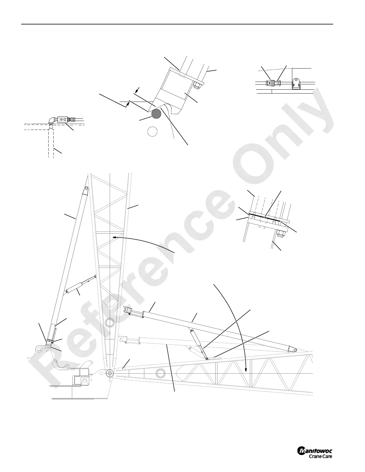
FIGURE 4-5
Physical Boom Stop Assembly
View A
A488
Engagement with pin should take place
1/3 to 1/2 of way down rear side of
saddle in both boom stop rod ends.
View B
View C
View D
Rod end must be snug against
shoulder of cylinder rod.
Rear side of saddle in both boom stop rod
ends must engage pin first. Damage to boom
stop will result if front side of saddle in either
rod end engages pin first.
Socket
Plug
Boom Stop
Rod End
Rod End
Guide
Boom Stop Tube
Boom Stop Cylinder
Rod end must be snug
against cylinder.
Boom Stop
Rod End
U-Shaped
Spacers
Boom Butt
Boom Stop
Tube
90° Maximum Angle
at Physical Stop
(See View A)
WORKING
Position
Strut Support in
Working Position
Strut Support in
Shipping Position
SHIPPING Position
(See View B)
(See View D)
Boom Stop
Cylinder
Strut
Cylinder
Boom Stop
Rod End
Check Valve –
Arrow must point
toward cylinder
Boom Stop
Cylinder
1/8 in (3,2 mm) gap between
ends of spacers.
(See View C)
Boom Stop
Pin
Air Cushioning Starts
at 80°
 Loading...


