Manitowoc Published 11-06-15, Control # 040-13 2-29
2250 SERVICE/MAINTENANCE MANUAL HYDRAULIC AND AIR SYSTEMS
established, the de-icer will automatically adjust the drip rate
proportionally to variations in the air flow. Push green lock
ring downward to lock setting after final adjustment. To
release, pull lock ring upward.
Maintenance
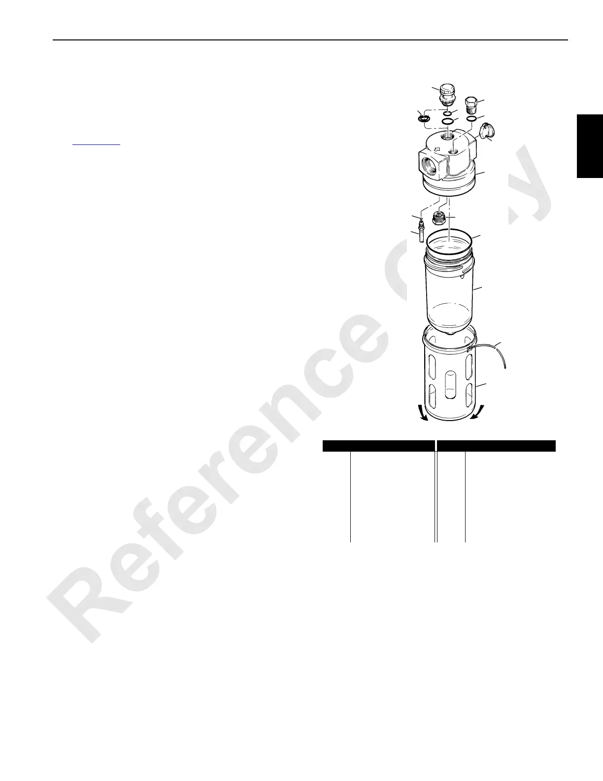
See Figure 2-33 for the following procedure.
To service the de-icer, shut off the air pressure. De-icer may
be disassembled without removal from air line.
If de-icer has transparent reservoir, remove guard (15) by
rotating guard around body (13) to wind out retaining spring
(14) through cutout in guard. Slide guard off body.
Unscrew and remove reservoir (9). Remove o-ring (3), fill
plug (4) and o-rings, (10 and 11) or seal (12), charge valve
(2), if used, siphon tube assembly (6) and check ball (8).
Flow sensor (1) should not be removed unless obviously
damaged. If removal is necessary, insert needle nose pliers
into inlet port in body (13) and grasp point of flow sensor.
Turn sensor approximately 1/4-turn either direction and push
out through outlet port of body.
Clean transparent reservoir using clear, warm water only.
Clean other pars using soap and water. Dry parts and blow
out internal passages using clean, dry compressed air.
Inspect each part carefully. Replace any parts which are
damaged.
At reassembly, make sure to reinstall flow sensor (1), if
removed, with point in direction opposite to flow arrow on
body (13). Apply a wipe coat of 44M grease (or equivalent) to
O-ring (3). Torque dome assembly (7) and charge valve (2),
if used, to 30 to 35 in/lb (3,4 to 4,4 N•m). Tighten siphon tube
(6) until snug only. Tighten reservoir (9) by hand until
arrowhead on reservoir is in line with or to the right of
arrowhead on body. Slide guard (15) onto body and align
retaining spring bead in guard with groove in body. Start
retaining spring (14) into groove through cutout in guard.
Rotate guard around body to 'wind in' the spring.
Filling
Fill reservoir with a good quality desiccant to level indicated
by maximum fill line. Do not overfill.
S116
Install
Remove
FIGURE 2-33
Item Description Item Description
1 Flow Sensor 9 Reservoir
2 Check Valve (charge) 10 O-Ring
3 O-Ring 11 O-Ring
4 Fill Plug 12 Seal
5O-Ring 13Body
6 Siphon Tube 14 Retaining Spring
7 Sight Feed Dome 15 Side Guard
8 Check Ball
6
8
2
9
5
7
1
3
4
14
12
15
13
10
11
 Loading...


