INTRODUCTION 2250 SERVICE/MAINTENANCE MANUAL
1-78
Published 11-06-15, Control # 040-13
EPIC
®
Programmable Controller
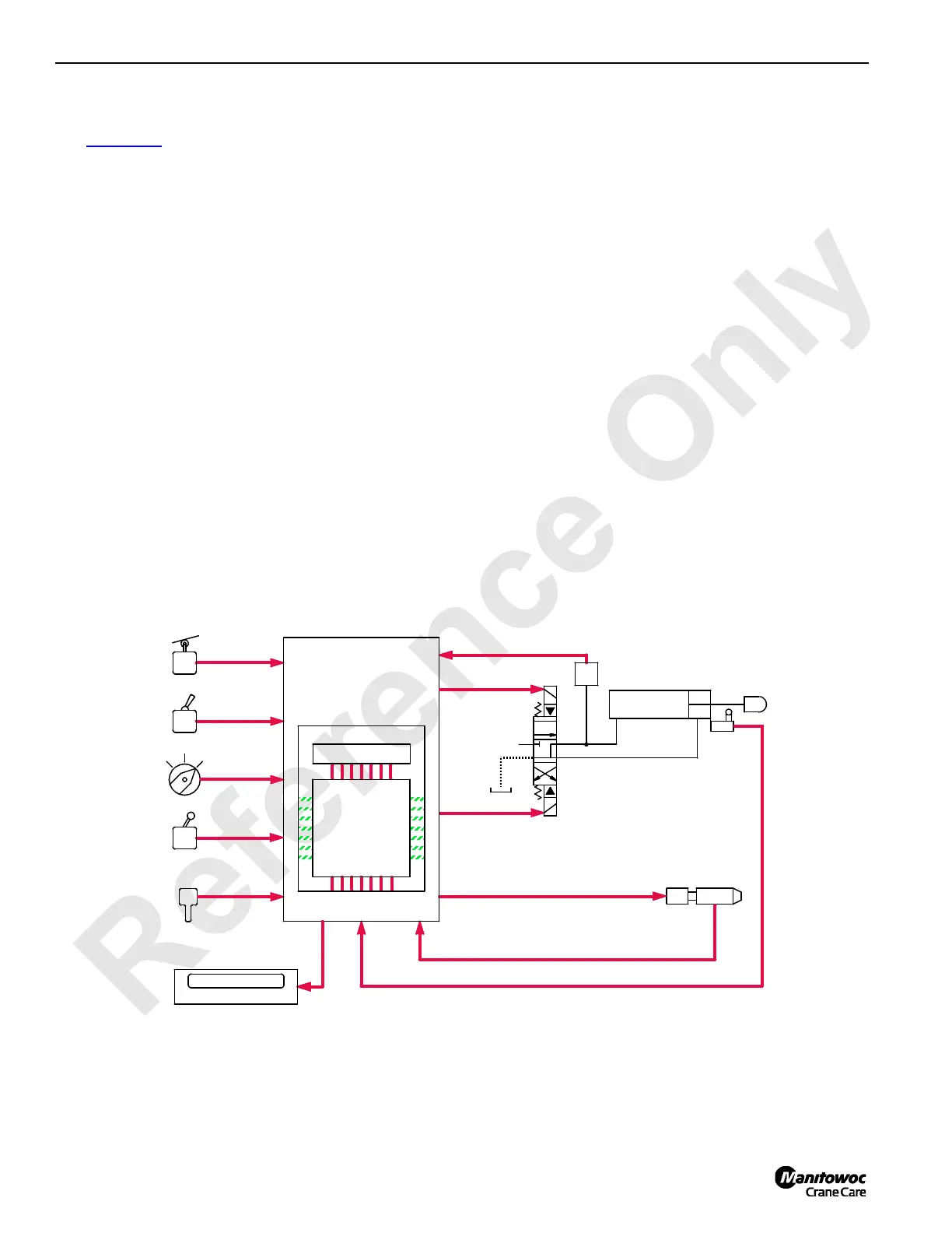
See Figure 1-47 for the following procedure.
The MAX-ER’s solenoid valves, cylinders, and motors are
monitored and controlled with electronic components of the
EPIC (Electrical Processed Independent Control) system.
The crane PC (Programmable Controller) and MAX-ER PC
are interfaced with serial wire RX3 (36) and TX3 (37). In this
section, the abbreviation (PC) assumes MAX-ER
Programmable Controller unless noted otherwise.
The PC receives and sends both analog and digital input/
output signals. Analog input/output signals are AC or DC
voltages or currents that are modulating. Digital input/output
signals are 12 volt nominal voltages that are either on or off.
The PC uses the binary system. The binary system is based
on multiples of 2, and only recognizes 0 for off or 1 for on
voltages. Basic counts of this system are exponents of the
number 2. These exponents are formed in words, called
bytes, of eight numbers each. The eight numbers are 1, 2, 4,
8, 16, 32, 64, and 128 for an 8-bit controller or a combination
of up to 255 bytes. These bytes represent electrical inputs to
the controller. The controller processes this information by
comparing it to programming requirements and data
information. The PC then provides appropriate output
commands to control devices.
Operating controls or control handles send input voltage
command signals to the MAX-ER or crane PC. The PC
compares these input voltages with feedback voltages
received from system monitoring sensors, memory
information, and directives entered into programming.
Monitoring sensors includes; limit switches, pressure
senders, encoders, counterweight level sensor, and back
hitch load pin sensor. The PC then sends a 12-volt output
signal to solenoid valves to control system cylinders, brakes,
pawls, and other controls.
NOTE: Rated Capacity Indicator/Limiter (RCL) system has
its own programmable controller and is part of the
EPIC system. For complete information see
separate Rated Capacity Indicator/Limiter
Operation manual.
Luffing jib (drum 5) operates the same as a load drum,
whether used as whip line or luffing jib. For drum 9 operation,
load drum holding pressure memory is used. Before
releasing drum disc brake, the PC reverses voltage polarity
to crawler travel (or main hoist in MAX-ER mode) pump
EDC’s, stroking crawler travel pumps in the up direction until
pressure memory is met. The PC then responds to left
control handle (drum 9) commands. See Operating Controls
topic in Section 3 of the MAX-ER Operator Manual for
description of drum numbers and handle indicator lights.
RM-01
SENSOR VOLTAGE INPUT
DIGITAL DISPLAY
MONITORING
VOLTAGES OUT
MEMORY
VOLTAGES
TO
COUNTS
TO
VOLTAGES
COMMAND
VOLTAGES IN
SENSOR DIGITAL INPUT
PROGRAMMABLE
CONTROLLER - PC
PROCESSING
CONTROL
HANDLES
SELECTORS
SWITCHES
LIMIT
SWITCH
REMOTE
CONTROL
P
HYDRAULIC
SOLENOID
HYDRAULIC
CYLINDER
LIMIT
SWITCH
PRESSURE
SENDER
T
VOLTAGE OUT
VOLTAGE OUT
VOLTAGE OUT
RIGHT SIDE CRANE
TYPICAL
BACKHITCH LOAD PIN
FIGURE 1-47
 Loading...


