Manitowoc Published 11-06-15, Control # 040-13 1-83
2250 SERVICE/MAINTENANCE MANUAL INTRODUCTION
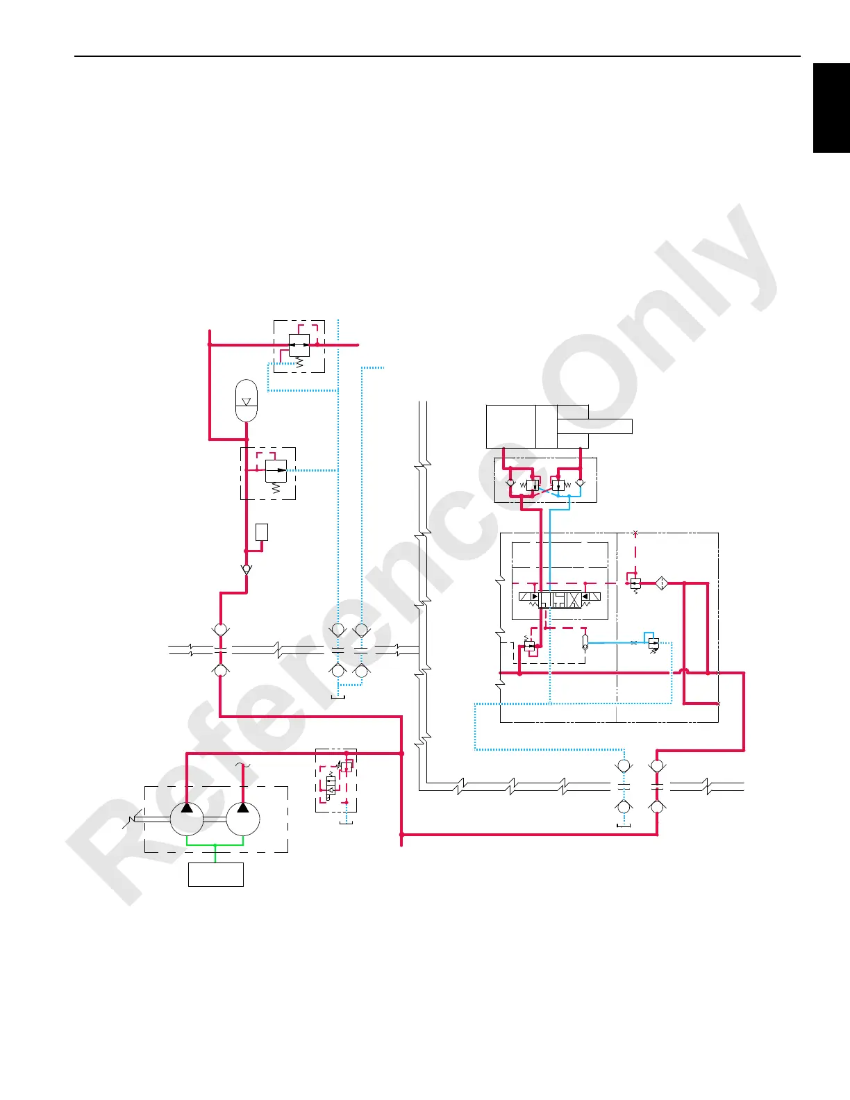
Tongue Cylinder Retract
When tongue cylinder switch is held in the UP retract
position, an input signal is sent to the PC. A 12-volt output
signal from PC enables the tongue cylinder retract solenoid
HS-51. Internal pilot supply pressure of 200 psi (14 bar)
enables selected spool to shift the tongue cylinder solenoid
valve. The crane PC sends an output signal to shift crane
auxiliary system disable valve HS-12, to block valve bypass.
Accessory system pressure increases to operate accessory
items.
Accessory system fluid enters MAX-ER accessory valve and
flows to free-flow check valve section of counterbalance
valve, entering rod end of the tongue cylinder to start
retracting the tongue cylinder. Fluid from piston end of
cylinder is blocked by free-flow check valve section of
counterbalance valve and flows through the flow restraining
section that has a relief setting of 2,800 psi (193 bar). Return
hydraulic fluid then exits counterbalance valve and passes
through MAX-ER accessory valve before returning to crane
hydraulic tank through return line. Release tongue cylinder
switch to OFF to lock tongue in position.
2200 psi
3000 psi (207 bar)
2000 psi
WHEELED COUNTERWEIGHT TRAILER
X
(13,8 bar)
200 psi
XX
X
C2C1
STOP CYLINDERS
FROM MAST
STOP CYLINDERS
TO MAST
MAST
RM-06
EXTEND
RETRACT
TONGUE CYLINDER
HS50
HS51
ACCUMULATOR
MAX-ER ACCESSORY VALVE
T
TO JIB STRUT
CYLINDERS
JIB STRUT
CYLINDERS
FROM
FIGURE 1-51
(207 bar)
3000 psi
PRESSURE
SENDER
ACCUMULATOR
MAST
(152 bar)
(138 bar)
ACCESSORY
TO CRANE
CRANE
MANIFOLD
SUCTION
AUX
FAN
VALVES
HS12
DISABLE
SYSTEM
AUXILIARY
NOTE: Past units have an
unloader valve that cuts in
at 2,300 psi (159 bar) and
cuts out at 2,900 psi (200
bar).
 Loading...


