BOOM 2250 SERVICE/MAINTENANCE MANUAL
4-4
Published 11-06-15, Control # 040-13
Adjustment
Maximum (MAX) Boom Stop
See Figure 4-2 for the following procedure.
1. For a crawler crane, travel the crane onto a firm level
surface or level the crane by blocking under the
crawlers.
For a truck crane, level the crane with the outriggers.
2. If necessary, adjust the position of limit switch (2a) with
relation to actuator bracket (4) as instructed in View B.
3. Loosen cap screws (5, View D) retaining MAX actuator
(3a) to actuator bracket (4).
4. Rotate MAX actuator (3a) CLOCKWISE in its slots so it
does not contact the limit switch roller when step 5
is
performed.
5. Raise the boom to specified Maximum Angle A
(Figure 4-1
) while monitoring the angle on the on the
mechanical indicator or on the operating conditions
screen of the front-console display.
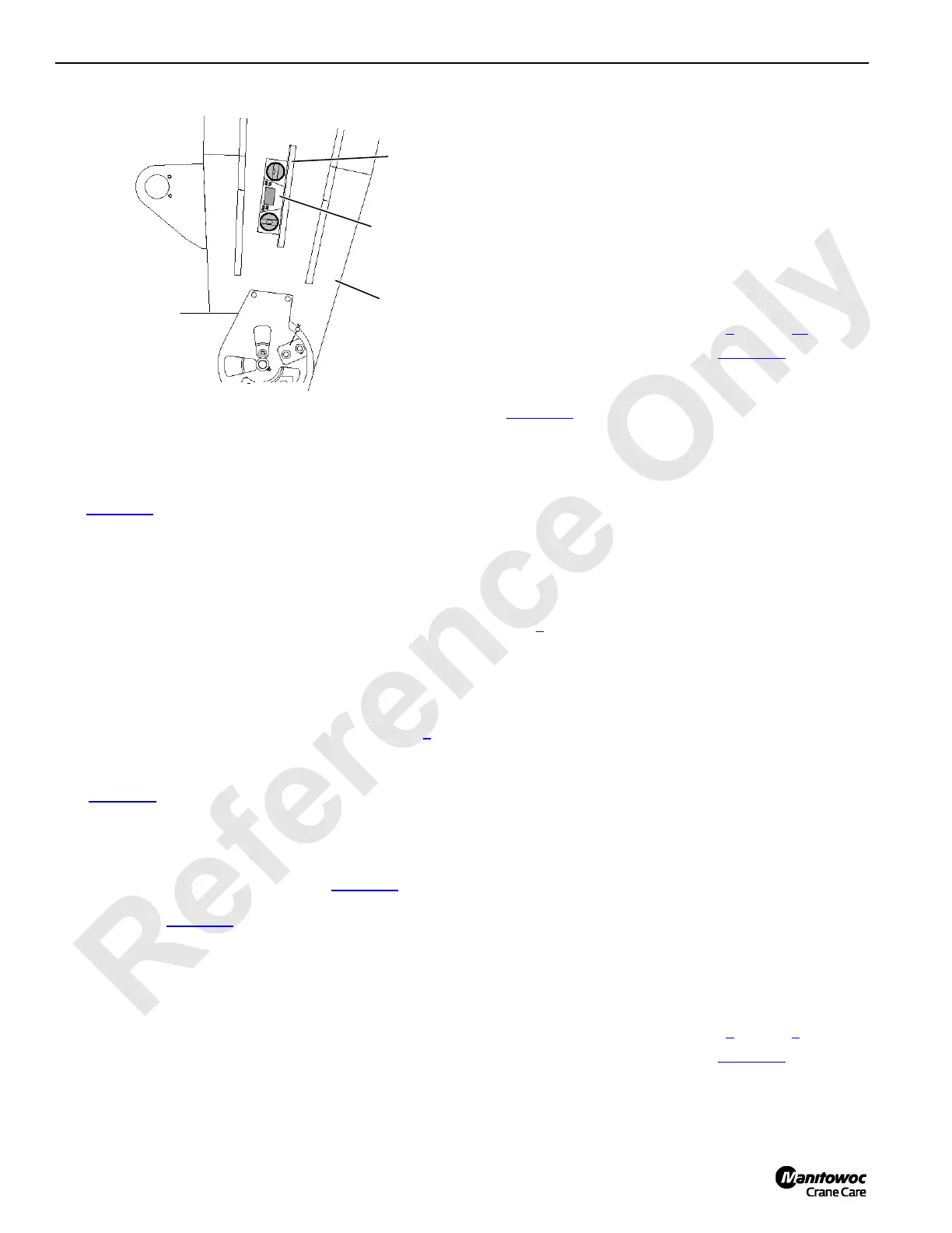
6. Verify that the boom is at the proper maximum angle:
a. Place an accurate digital level (7, Figure 4-3
) on the
centerline of the boom butt. Maximum Angle A
given in Figure 4-1
should appear on digital level.
b. Raise or lower the boom as necessary.
7. Rotate MAX actuator (3a, View A) against the roller of
limit switch (2a) until the limit switch just “clicks” open
and hold.
8. Check the position of MAX actuator (2a) with relation to
actuator bracket (4) as instructed in View C).
9. Securely tighten cap screws (5) to secure actuator (3a).
10. Test the adjustment as follows:
a. Lower the boom several degrees below the
specified maximum angle.
b. Slowly raise the boom.
c. Boom must stop at specified Maximum Angle A.
If the boom does not stop at the specified angle:
- Stop raising the boom (move control handle to
off).
- Lower the boom several degrees below the
specified angle.
- Repeat adjustment steps 5
through 10.
11. Seal the adjustment as shown in Figure 4-2
, View D.
Minimum (MIN) Boom Stop
See Figure 4-2 for the following procedure.
NOTE The slots in MIN actuator (2b) allow the minimum
boom angle to be adjusted to any angle between 4°
above or below horizontal.
1. If necessary, adjust the position of limit switch (2b) with
relation to actuator bracket (4) as instructed in View B.
2. Loosen cap screws (5, View D) retaining MIN actuator
(2b) to actuator bracket (4).
3. Rotate MIN actuator (3b) COUNTERCLOCKWISE in its
slots so it does not contact the limit switch roller when
step 4
is performed.
4. Lower the boom to the desired minimum angle.
5. Rotate MIN actuator (3b) against the roller of limit switch
(2b) until the limit switch just “clicks” open and hold.
6. Check the position of MIN actuator (3b) with relation to
actuator bracket (4) as instructed in View C.
7. Securely tighten cap screws (5) to secure actuator (3b).
8. Test the adjustment as follows:
a. Raise the boom several degrees above the desired
minimum angle.
b. Slowly lower the boom.
c. The boom should stop at the desired minimum
angle. If the boom does not stop at the desired
angle:
- Stop lowering the boom (move control handle to
off).
- Raise the boom several degrees above the
desired minimum angle.
- Repeat adjustment steps 4
through 8.
9. Seal the adjustment as shown in Figure 4-2
, View D.
FIGURE 4-3
1
7
8
#44 Boom Only

 Loading...


