5
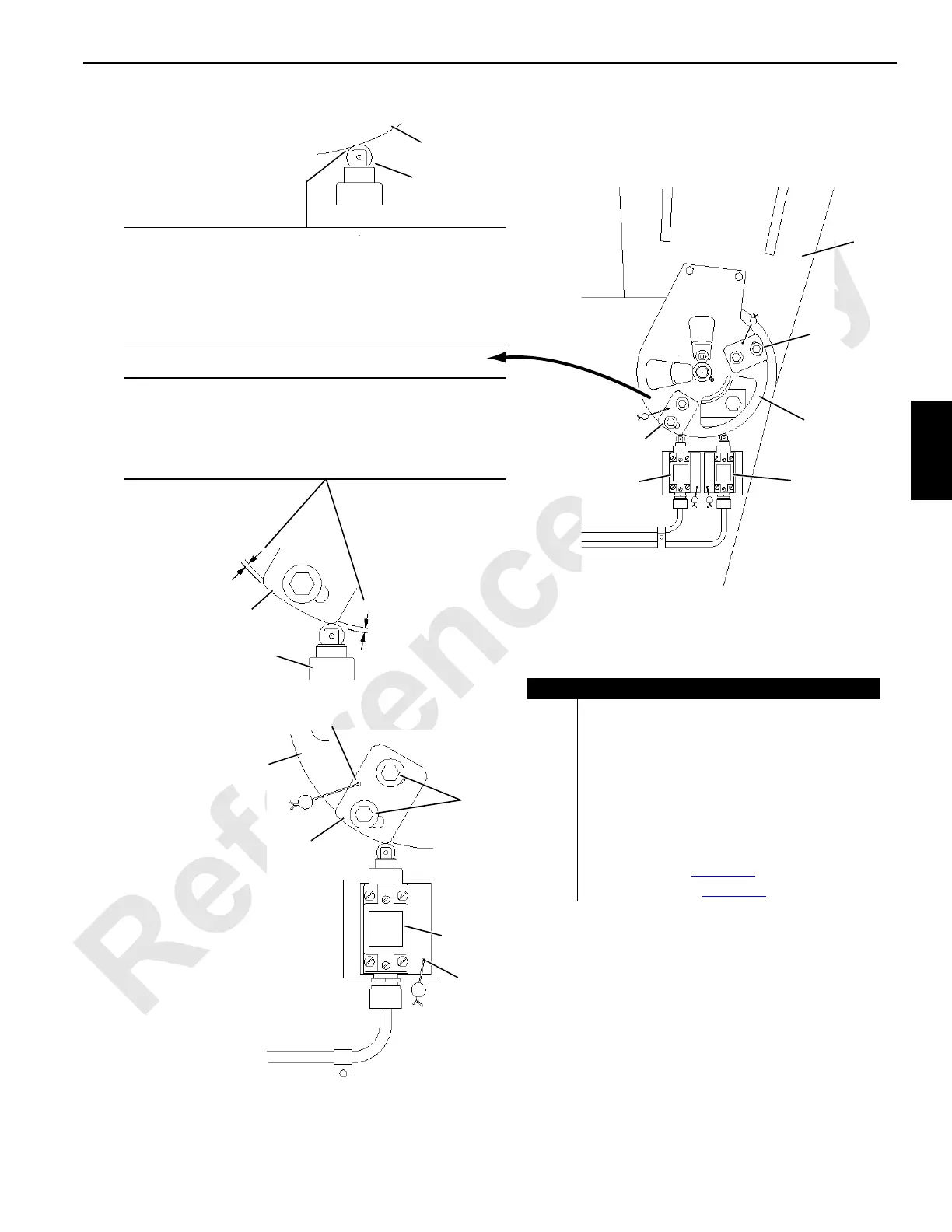
FIGURE 4-2
Item Description
1 Boom Butt
2a Limit Switch (MAX)
2b Limit Switch (MIN)
3a Actuator (MAX)
3b Actuator (MIN)
4 Actuator Bracket
5 Cap Screw with Flat Washer and Lock Washer
6 Dowel Roll Pin with Seal Lead and Wire
7 Digital Level (see Figure 4-3
)
8 Level Support (see Figure 4-3
)
Q
Q
Drill for 1/8 in (3,2 mm) dowel.
Install wire and seal lead after
adjustments are made.
3a or 3b
2a or 2b
6
4
CAUTION
Check this distance after adjusting limit switch. Distance from
both ends of MAX actuator to outside edge of actuator bracket
must be equal. Limit switch could be damaged from over-travel if
either end of actuator is cocked.
VIEW A
VIEW D
(typical)
VIEW B
CAUTION
Before adjusting limit switch, move limit switch up or down in
slots so edge of roller is even with edge of actuator bracket.
Limit switch will not trip open if positioned too low in slots. Limit
switch could be damaged from over-travel if positioned too high
in slots.
1
4
3b
2b
3a
2a
Q
6
4
2a or 2b
2a or 2b
VIEW C
3a or 3b
 Loading...


