HYDRAULIC AND AIR SYSTEMS 2250 SERVICE/MAINTENANCE MANUAL
2-18
Published 11-06-15, Control # 040-13
Initial Start-Up
The following procedure requires two people: one to start
engine and monitor pressures on diagnostic screens and
one to monitor bleed lines and close bleed valves.
1. Calibrate pressure senders as described in above topic.
2. Open shut-off valve in pump suction line (Figure 2-21
).
Pumps can be damaged from cavitation if this step
is not performed.
3. Connect bleed lines equipped with shut-off valves to
gauge coupler at each pressure sender (Figure 2-16
).
4. Open shut-off valve in each bleed line. Use a suitable
container to catch oil.
5. Remove adjusting screw from fan and pilot pressure
relief valves (Figure 2-22
and Figure 2-23). Then
reinstall screws approximately 1/4 in (6 mm) and
securely tighten lock nuts. Serious damage can occur to
system components if this step is not performed before
starting engine first time.
6. With all controls off, start and run engine at lowest
possible speed.
7. Have one person bleed pressure senders while a
second person checks pressures.
8. Bleed pressure senders:
a. Observe oil flowing from bleed line at each pressure
sender (Figure 2-16
).
b. Close each bleed valve when a clear, steady stream
of oil appears (no air bubbles in oil).
c. If oil does not flow from any bleed line, determine
cause and correct.
9. On diagnostic screens, check pump pressures for load
drums, boom hoist, swing, and travel pumps:
a. Make sure pressure reading for each pump is 200 –
500 psi (13.8 – 34,5 bar). Pump pressures will be
adjusted to final setting later in this procedure.
b. If pump pressures are not within specified range,
stop engine immediately. Determine cause of
faulty pressure and correct.
10. Stop the engine.
11. Remove bleed lines from gauge couplers at each
pressure sender.
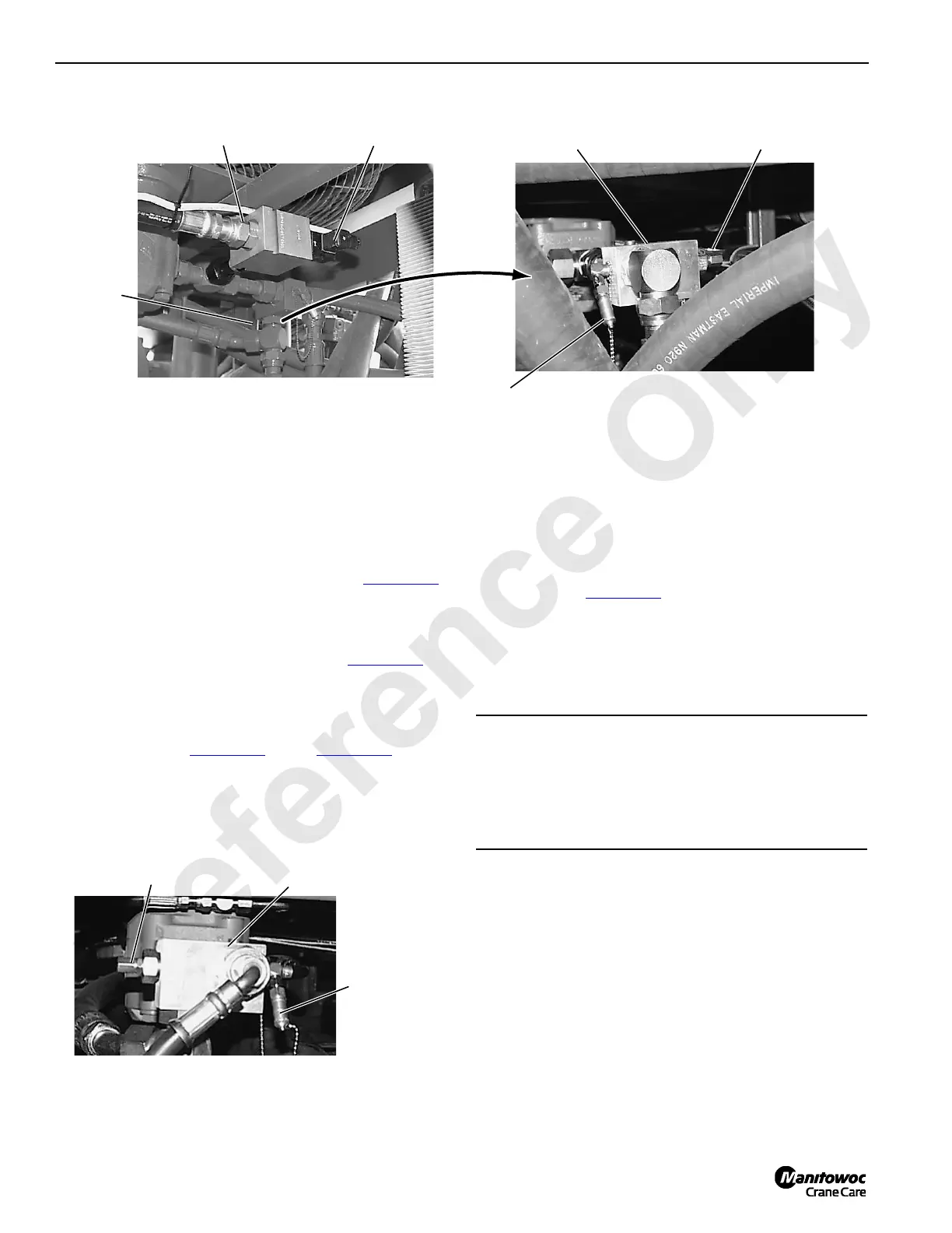
FIGURE 2-22
Fan Bypass Valve (optional)
P970
P971
Electric Plug
Fan Relief
Valve
Adjusting Screw
(with lock nut and protective cap)
Fan Relief Valve
1/8 inch Gauge Coupler
(with protective cap)
Access at Left End of Radiator
FIGURE 2-23
Adjusting Screw (with lock
nut and protective cap)
P972
1/8 in. Gauge
Coupler (with
protective cap)
Access at Right End of Radiator
Pilot Pressure
relief Valve
CAUTION
Equipment Damage!
Check pump pressure during first two minutes of
operation. If pressure for any pump is not within specified
range, shut down engine immediately to prevent pump
damage. Troubleshoot to determine cause of problem.
 Loading...


