INTRODUCTION 2250 SERVICE/MAINTENANCE MANUAL
1-66
Published 11-06-15, Control # 040-13
Boom Butt Handling Cylinder
See Figure 1-37 and Figure 1-39 for the following procedure.
Power is available to setup remote control when the cable is
connected at air valve junction box on left side of rotating bed
and engine is running.
Boom Butt Handling Cylinder Extend
When power button is pressed and boom butt cylinder switch
is held in the up extend position, an input signal is sent to the
PC. The PC sends a 12 volt output signal to auxiliary system
disable relief valve HS-12 that adjust system pressure to
3,500 psi (241 bar).
Boom butt handling cylinder extend solenoid HS-15 is
enabled by the PC to shift the solenoid valve in the extend
position. Hydraulic fluid enters upper accessory valve and
flows through variable output control valve HS-20 and
hydraulic quick disconnect to lower accessory valve.
Hydraulic fluid exits the valve assembly and flows through
the free-flow check valve section of counterbalance valve.
Hydraulic fluid then enters piston end of boom butt handling
cylinder, extending cylinder to raise the boom butt.
Fluid from rod end of cylinder is blocked by the opposite side
free-flow check valve section of counterbalance valve and
flows through the flow restraining section with a relief setting
of 3,000 psi (207 bar). Counterbalance valve act as a
deceleration control with a 3:1 pilot ratio. Hydraulic fluid flows
through boom butt handling cylinder valve to tank through
the hydraulic quick disconnect.
When power button or boom butt cylinder switch is released,
the PC sends a 0 volt output to shift spool of solenoid HS-15
to center position.
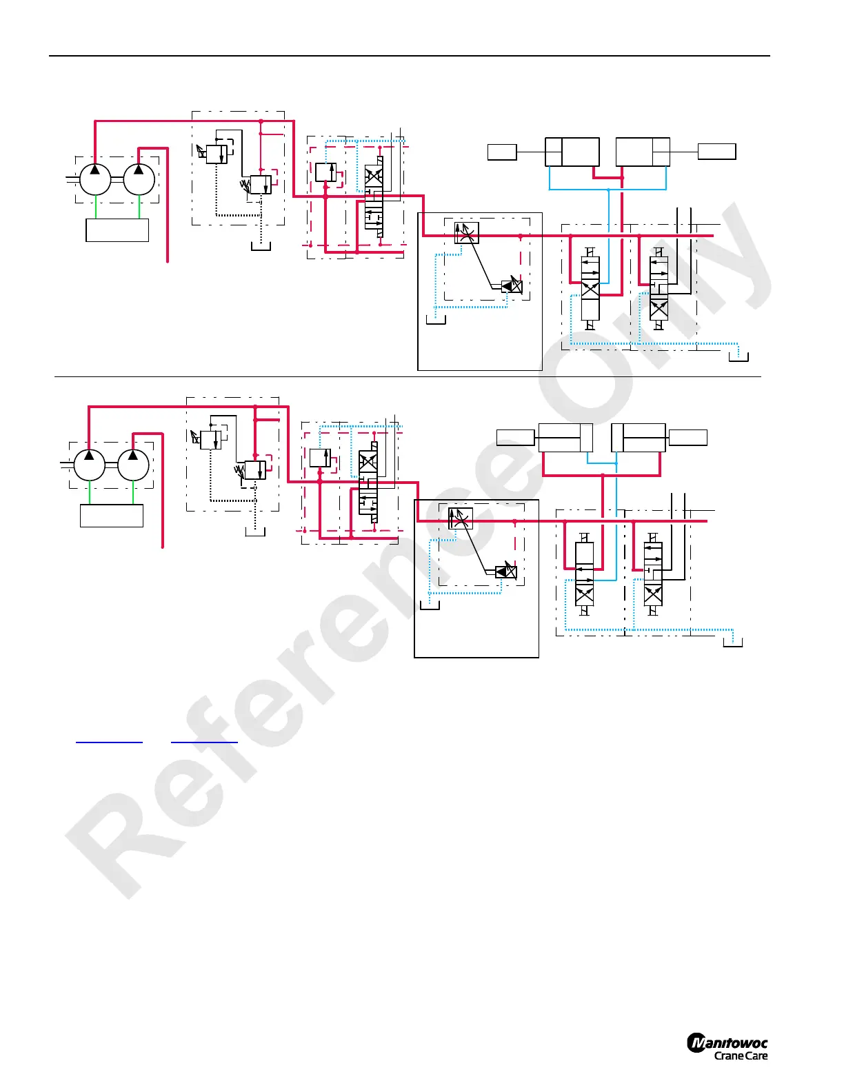
BOOM HINGE PINS ENGAGE
RF-33
AUXILIARY SYSTEM
RELIEF VALVE
HS-12
AUXILIARY PUMP
FAN PUMP
TO FAN
DISABLE
CIRCUIT
UPPER ACCESSORY VALVE
HS-11
HS-10
LOWER ACCESSORY VALVE
x
BOOM HINGE PINS DISENGAGE
RF-34
AUXILIARY SYSTEM
SUCTION
MANIFOLD
RELIEF VALVE
HS-12
AUXILIARY PUMP
FAN PUMP
TO FAN
DISABLE
CIRCUIT
UPPER ACCESSORY VALVE
HS-11
HS-10
LOWER ACCESSORY VALVE
x
VARIABLE OUTPUT VALVE
0 TO 15 gpm (57 l/min)
VARIABLE OUTPUT VALVE
0 TO 15 gpm (57 l/min)
SUCTION
MANIFOLD
X
X
FIGURE 1-38
(PAST PRODUCTION)
(PAST PRODUCTION)
 Loading...


