Manitowoc Published 11-06-15, Control # 040-13 2-43
2250 SERVICE/MAINTENANCE MANUAL HYDRAULIC AND AIR SYSTEMS
Adjustment
1. Shut down the crane.
2. Discharge system air pressure.
3. Disconnect crane source air line piping at pressure
switch that needs adjustment.
4. Remove cover screw (4) and cover.
5. Connect a calibrated pressure source with gauge to the
1/4” NPT fitting on the air sensor inlet ensuring there are
no air leaks.
6. Connect one lead of the tester to either the N.C. terminal
or the N.O. terminal of the limit switch, depending on the
circuit application. Ground the other lead of the tester.
7. Connect the D.C. voltage power supply to the COM
(common) terminal of the limit switch.
8. If the pressure switch is wired normally closed,
proceed as follows:
a. Turn the adjusting screw all the way in and then out
until it just touches the plunger.
b. Increase air pressure to the specified point (tester
light should go OFF).
c. Turn the adjusting screw IN until the tester light
comes ON.
9. If the pressure switch is wired normally open, proceed
as follows:
a. Turn the adjusting screw all the way in.
b. Increase air pressure to the specified point.
c. Turn the adjusting screw OUT until the tester light
comes ON.
10. Always recheck set points after adjustments are made.
11. Disconnect the D.C. voltage power supply, calibrated air
supply, and tester.
12. Reinstall air pressure switch.
13. Start crane and allowing system to reach operating
pressure. Activate corresponding circuit to test and
confirm pressure switch trip point.
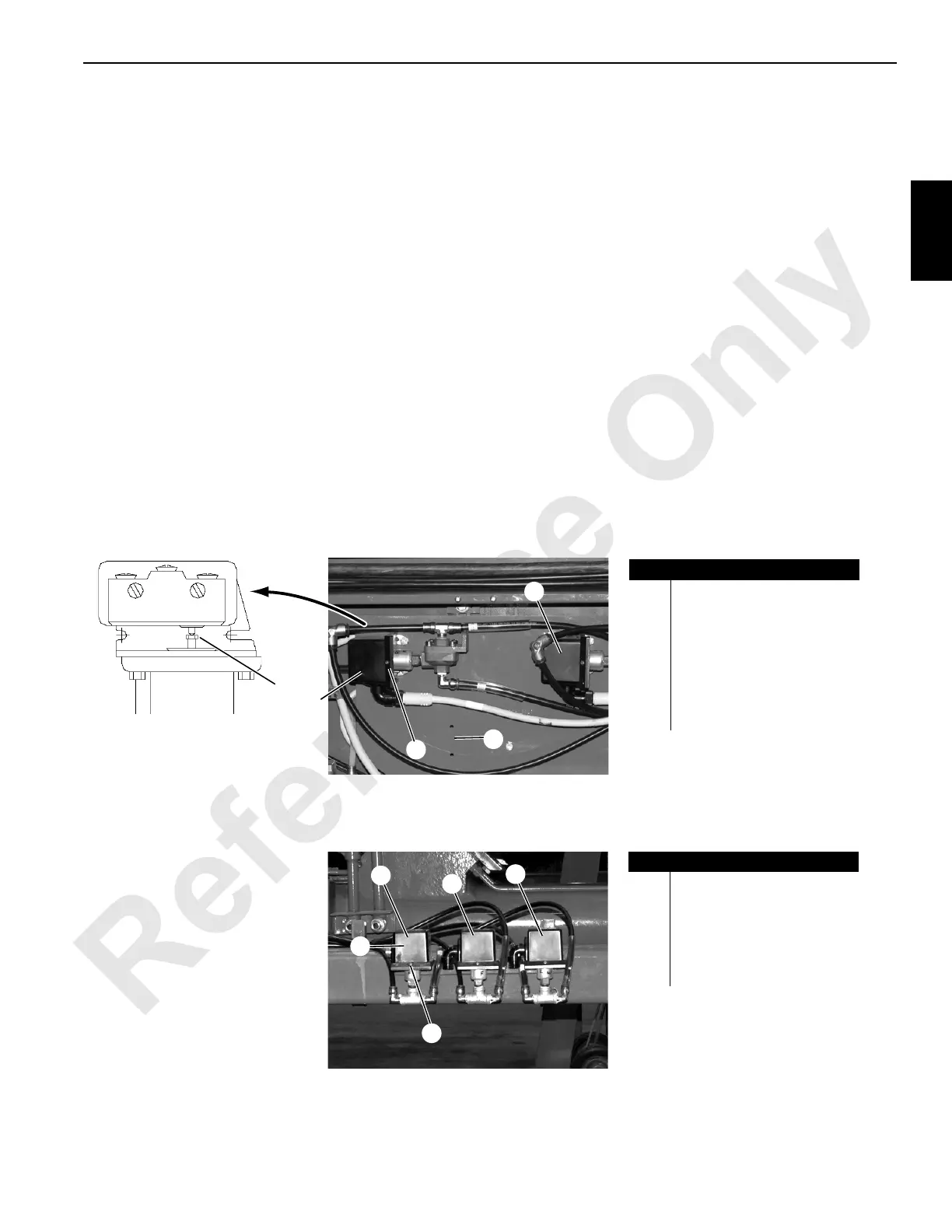
P2487_1
673356
Item
Description
1
Drum 3 (Left Rear)
Pressure Switch
2
Drum 2 (Rear/Right Rear)
Pressure Switch
3
Drum 1 (Front) Pressure
Switch (not shown)
4 Cover Screw (typical)
5 Switch Adjustment Screw
5
Left Side of Crane
1
2
FIGURE 2-43
IMG_6844
Item
Description
6 Has No Function
7 Has No Function
8 Pressure Switch Cover
9 Cover Screw (typical)
10
Low System Air Pressure
Safety Switch
Left Side of Crane Under Cab
 Loading...


