Manitowoc Published 11-06-15, Control # 040-13 5-9
2250 SERVICE/MAINTENANCE MANUAL HOISTS
DRUM BRAKE INSPECTION AND
ADJUSTMENT
Description
Each drum brake consists of an external, contracting band-
type brake and two actuators. On single drum shafts, the
brake is mounted on the left end of the drum. On split drum
shafts, a brake is mounted on the outboard end of both
drums. Independent drum drive has two brakes, one
mounted on the left end of drum shaft and the other mounted
on the right end.
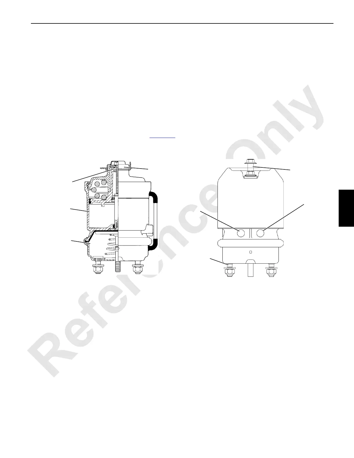
NOTE: There are two types of brake actuators used. A
past production type actuator and a current
production type actuator is shown in Figure 5-6
.
Customers ordering replacement brake actuators
will receive the current type.
Each actuator has two chambers which provide two separate
braking systems for each load drum:
• The spring chamber provides a spring-applied, air-
released parking brake. In the full power mode, the
parking brake is applied and released automatically by
the load drum control.
• Only one service chamber is used. It provides an air-
applied, spring-released working brake. Braking control
is variable, from fully applied to fully released, through
the use of a treadle valve.
The operator shall be seated and the engine must be running
to operate the drum controls and parking brakes during the
inspection, adjustment, and overhaul steps. The drums are
automatically parked and the handles are inoperable when
the operator is out of the seat or the engine is off.
FIGURE 5-6
Drum Brake Actuator Identification
(shown with working and parking brakes released)
Brake Release
Bolt (installed)
S153
Spring Chamber
(Parking Brake)
Service Chamber
(Working Brake)
Dust
Cap
Past Production
Actuator
Mounting Studs
Service Brake Port
(Working Brake)
Current Production
Actuator
192789-2
Service Brake Port
(Parking Brake)
Brake Release
(Shown Caged)
 Loading...


