TROUBLESHOOTING 2250 SERVICE/MAINTENANCE MANUAL
10-52
Published 11-06-15, Control # 040-13
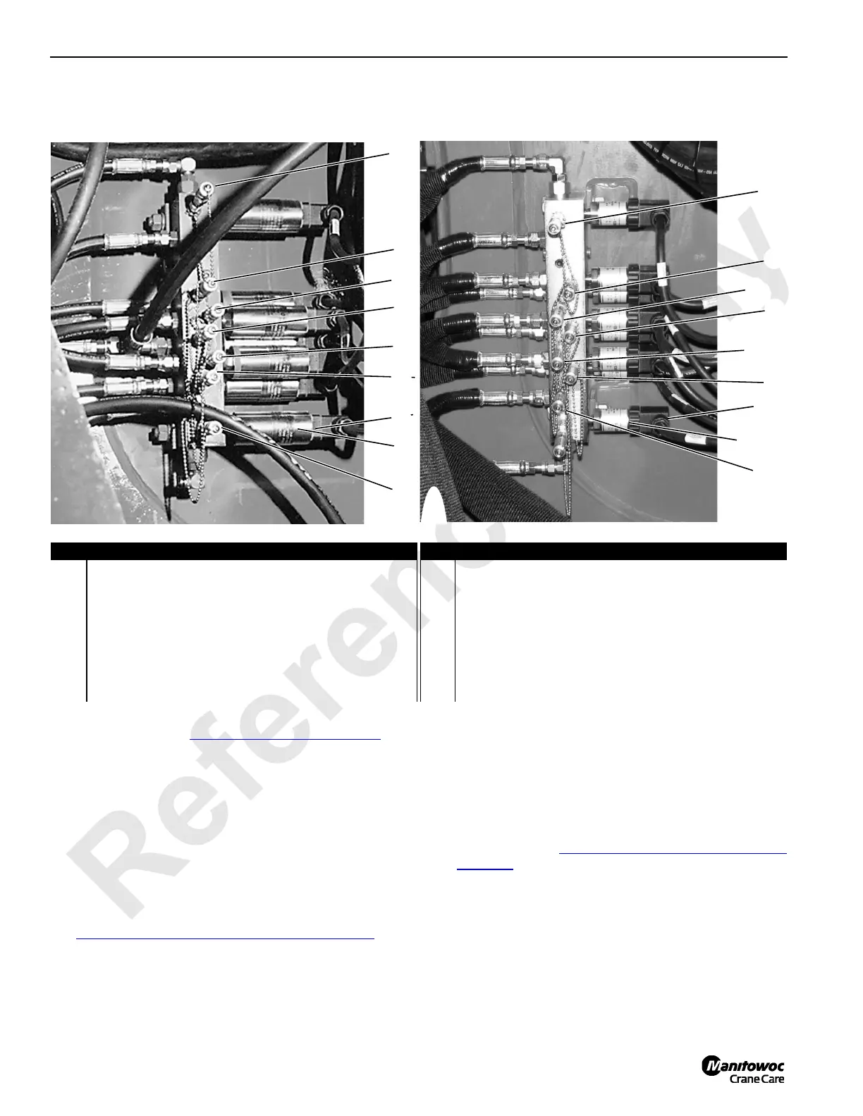
Test 17 — Checking Pump Charge Pressure and Electrical Test
Component charge systems can be checked at the M1, M2
or M3 gauge ports (see Test 7 — Location of Motor Ports
). To
check pump charge pressure:
• Install a 0 – 600 (0 – 42 bar) gauge at the desired system
diagnostic gauge coupler on pressure transducer
manifold.
• Start the system and record the charge pressure at
engine idle speed.
• No hydraulic systems should be enabled.
• A reading of 350 psi (24 bar) is system charge pressure.
• A reading of less than 350 psi (24 bar) indicates a
charge pressure relief adjustment is necessary. See
Test 19 — Adjusting Pump Charge Pressure Relief
.
Test the voltage and resistance of a system pressure
transducer with a standard test plug adapter (can be ordered
from Manitowoc Cranes, Inc.) and a digital multi-meter.
To test incoming power at desired pressure transducer:
• Connect the test plug adapter between pressure
transducer and DIN plug.
• Connect white (positive) and black (negative) wires from
adapter cable to digital multi-meter jacks.
• Check for 12 volts DC.
• If this reading is not obtained, check 5 amp F12 fuse at
fuse panel (see Test 12 — Testing for Voltage at the
Fuse Box).
To test voltage output from pressure transducer to the PC:
• Engine must be off and power on, with all brakes and
locks engaged.
• Connect green (positive) and black (negative) wires to
digital multi-meter jacks.
• Check for 1.00 to 1.04 volts DC.
1
P6706
2
3
4
5
6
8
9
7
Previous Production
Current Production –SN 2251179, 2251183, 225185 & up
P930
1
2
3
4
5
6
8
9
7
Item Description Item Description
1
Front Drum/travel (Previous) or Right travel (Current)
system pressure port
6 Swing left system pressure port
2 Boom hoist system pressure port 7
Front drum/travel (Previous) or Left travel (Current)
charge pressure port
3
Load Drum (Previous) or Hoist system (Current)
pressure port (pump outboard)
8 DIN connector (electrical test)
4
Load Drum (Previous) or Hoist charge pressure port
(pump inboard)
9 Pressure transducer
5 Swing right system pressure port

 Loading...


