Manitowoc Published 11-06-15, Control # 040-13 1-33
2250 SERVICE/MAINTENANCE MANUAL INTRODUCTION
EPIC
®
Programmable Controller (PC)
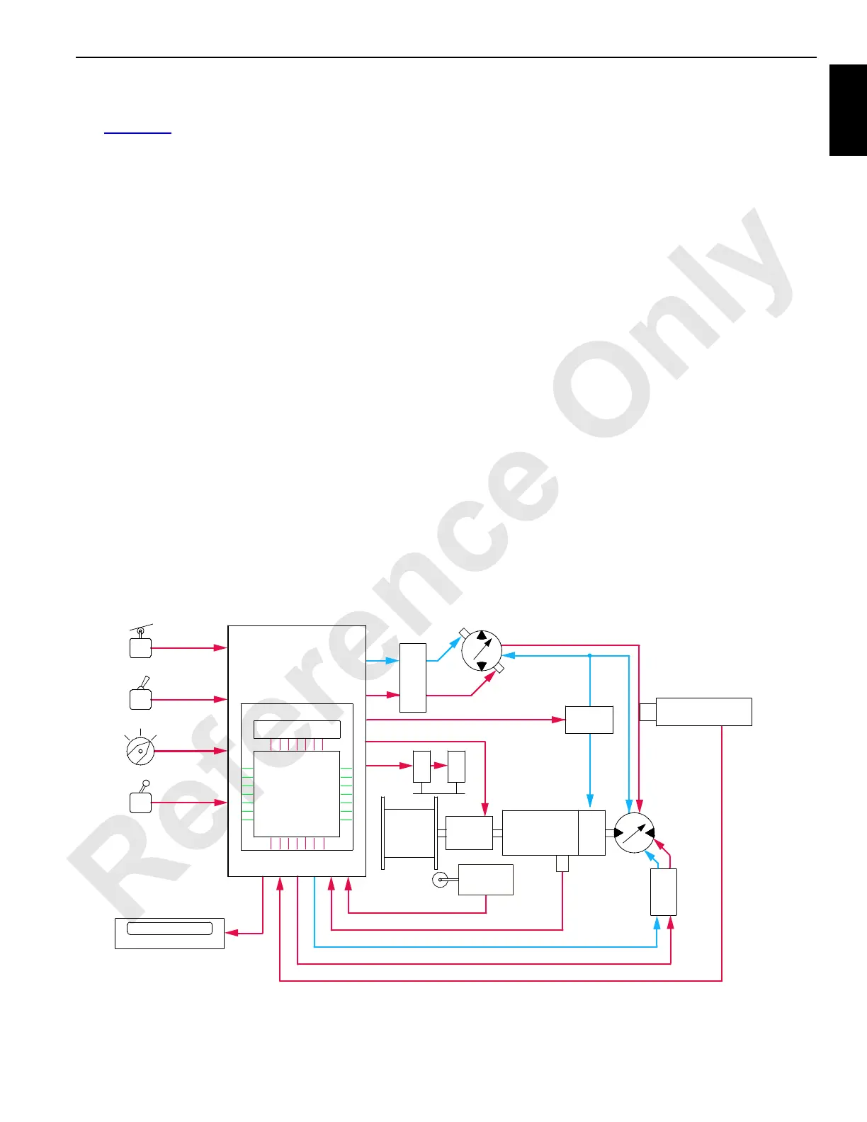
See Figure 1-16 for the following procedure.
The Model 2250 crane’s boom, load lines, swing, crawler
tracks, and accessory components are controlled
electronically with the EPIC (Electrical Processed
Independent Control) system. This simplifies the crane's
electrical control system by avoiding mechanical control
switches and relays. Standard or custom programming
allows the PC (Programmable Controller) to automatically
adjust each operational mode's acceleration rate and speed,
apply brakes, and engage clutches.
The PC receives and sends both analog and digital input/
output voltages. Analog input/output voltages are either AC
or DC variable voltages or currents that are in a pulse train.
Digital input/output voltages are 12 volt nominal voltages that
are either 0 = off or 1 = on.
The PC uses the binary system. The binary system is based
on binary multiples of two and only recognizes 0 = off or 1 =
on. Basic counts of this system are exponents of the number
two. These exponents are formed in words, called bytes, of
eight numbers each. The eight numbers are 1, 2, 4, 8, 16, 32,
64, and 128 for an 8-bit controller or a combination of up to
255 bytes. These bytes represent electrical inputs/outputs to
the controller.
The controller processes the information by comparing it to
programming requirement and data information. The PC
then provides appropriate output commands to crane control
devices. See Crane Diagnostics topic in Section 10 of this
manual.
Digital Display
Digital display screen on front console shows operating
conditions, operating limits, and system faults monitored by
the PC. Access information by scrolling to the desired
display screen with scroll switch. System messages are
shown in Tables in Digital Display Readings in Section 3 of
the Operator Manual.
Rated Capacity Indicator/Limiter (RCL)
The RCL system has its own PC (Programmable Controller)
and is part of the EPIC system. Load charts are specific for
each crane model. For complete information see separate
Rated Capacity Indicator/Limiter Operation manual.
Crane Modes
• Standard mode is for all normal load-handling
operations.
• In Setup mode, the program allows limited operation, but
boom-up limit is bypassed.
• In Luffing Jib mode, the program allows standard mode
load handling operations plus luffing jib operation.
• In Tandem Drum mode, the program allows operation of
both load drums on a split drum shaft, or both front and
rear load drums are operated at the same time in full
power operation with a single control handle.
RF-08
COMMAND VOLTAGES IN
MONITORING
VOLTAGES OUT
BRAKES
DIGITAL DISPLAY
VOLTAGES
TO
COUNTS
TO
VOLTAGES
MEMORY
PROCESSING
PROGRAMMABLE
CONTROLLER - PC
SENSOR VOLTAGES IN
MOTOR SPEED SENSOR (IF CLUTCH EQUIPPED)
PRESSURE
SENDERS
OPERATIONAL VOLTAGES OUT
PUMPS
EDC
BRAKE
VALVE
DRUM
SPEED
SENDERS
MOTORS
CLUTCH
IF
EQUIPPED
DRUMS
SELECTORS
CONTROL
HANDLES
SWITCHES
LIMIT
SWITCHES
GEAR
REDUCER
PCP
B
R
A
K
E
FIGURE 1-16

 Loading...


