Manitowoc Published 11-06-15, Control # 040-13 1-81
2250 SERVICE/MAINTENANCE MANUAL INTRODUCTION
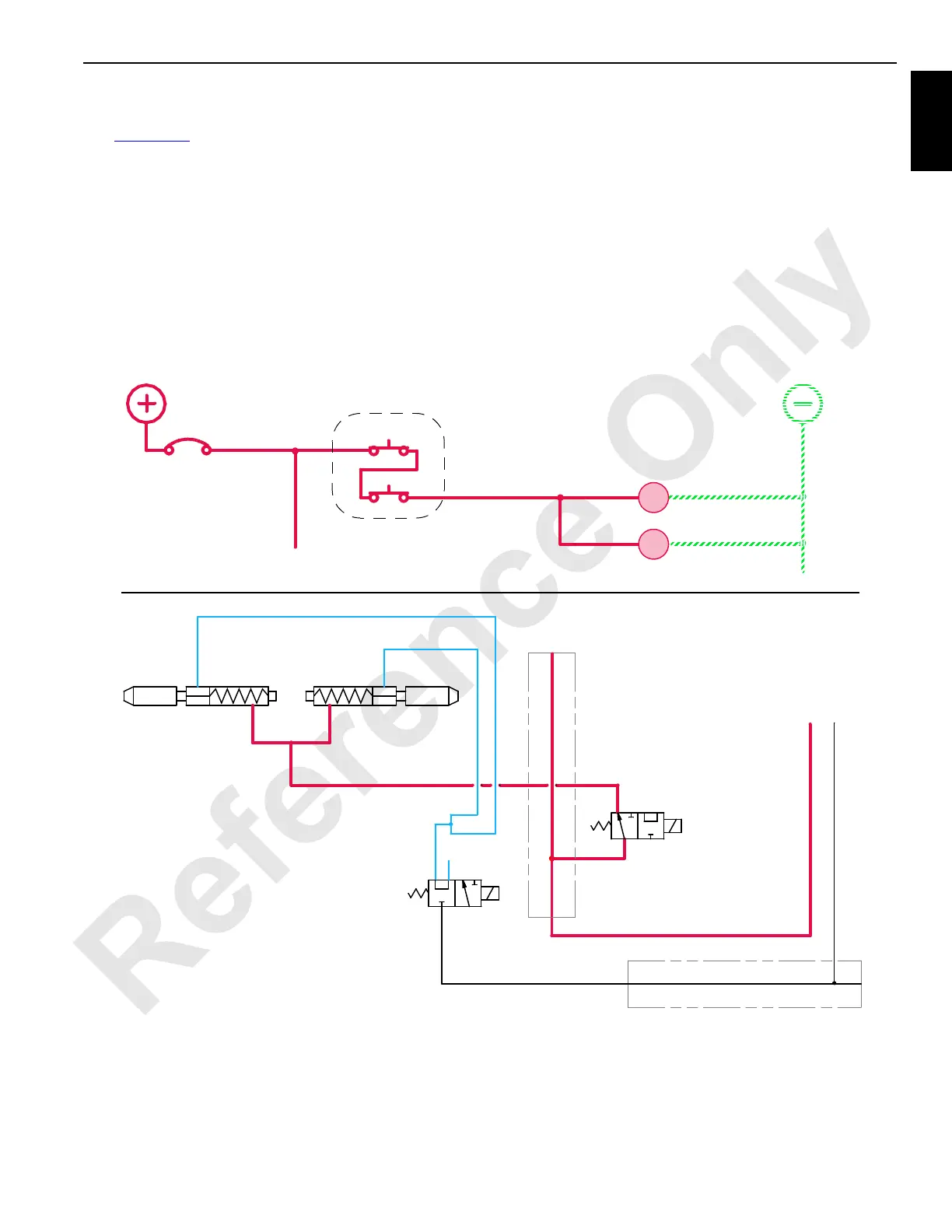
Back Hitch Pins
See Figure 1-49 for the following procedure.
Back hitch pins are retracted from telescopic back hitch strap
at assembly/disassembly. Power is available to mast back
hitch pins remote switch when power cable (W29) is plugged
into receptacle at bottom of main junction box at left side of
crane and engine is running. The mast back hitch pins
remote switch is operative only if crane is in Standard or
Setup mode.
Back Hitch Pins Extend/Retract
Each back hitch pin cylinder is spring-returned to extended
position. In this position, back hitch pins normally closed air
solenoid AS-1 is disabled and normally opened air solenoid
AS-2 is also disabled. This allows air flow from manifold
through AS-1 to piston end of pin cylinders. When power
(ON) button and retract (OUT) buttons are pressed and held,
back hitch pins air solenoids AS-2 and AS-1 are both
enabled to retract the back hitch pins. Air then flows through
solenoid AS-2 to rod end of back hitch pin cylinders. Back
hitch pin cylinders then retract to move pins out of
engagement while air from piston end of cylinder exhausts to
atmosphere through air solenoid AS-1.
8K
60M
N/O
N/C
0
AS-2
AS-1
15 AMP
CB
5A
8K
RM-04
MAST BACKHITCH
PIN CYLINDER
AS-2
AS-1
MAST BACKHITCH
PIN CYLINDER
MAST BACKHITCH
PIN DISINGAGE
MAST BACKHITCH
PIN ENGAGE
P
E
A
A
E
P
FROM MAIN
AIR MANIFOLD
MANIFOLD
MANIFOLD
M
MAST BACKHITCH PINS
REMOTE
TO MAX-ER REMOTE
P
R
ELECTRICAL CIRCUIT
AIR SYSTEM
RM-03
FIGURE 1-49
 Loading...


