Rotating Bed Jacking Cylinders
1. Stop the engine.
2. Jacking cylinders will be extended during this procedure.
a. Rotate jacking cylinders away from rotating bed so
they cannot contact anything.
b. Warn all personnel to stand clear of cylinders.
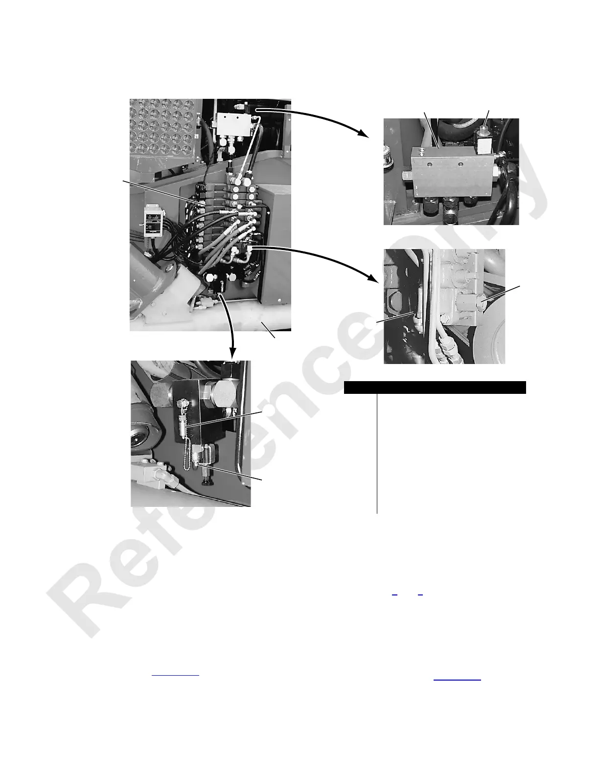
3. Connect an accurate 0 to 6,000 psi (0 to 413 bar)
hydraulic pressure gauge to gauge coupler on auxiliary
system relief valve (Figure 2-26
, View A).
4. Start and run the engine at 1,500 RPM.
5. Fully extend one jacking cylinder until it bottoms out
(stall hydraulic system). Gauge pressure should be
2,200 to 2,300 psi (152 to 158 bar).
6. Repeat steps 4
and 5 for each jacking cylinder, one at a
time.
7. If specified pressure is not indicated for any cylinder,
determine cause and correct.
8. Fully retract and store cylinders when done.
9. Stop engine and remove gauge from coupler on auxiliary
system relief valve (Figure 2-26
, View A). Install
protective cap over coupler.
FIGURE 2-26
P923
P975
P922
P974
View C
View B
View A
Access at Right Rear
Corner of Rotating Bed
Item
Description
1 Auxiliary System Valve Assembly
2 Jacking Cylinder
3 Proportional Flow Control Valve
4 Bleed Screw
5 Auxiliary System
6
Main Relief Valve
(with lock nut and adjusting screw)
7 Valve1/8 inch Gauge Coupler
8
Auxiliary System Relief Valve
(with lock nut and adjusting screw)
1
2
3
4
5
7
6
8
 Loading...


