HYDRAULIC AND AIR SYSTEMS 2250 SERVICE/MAINTENANCE MANUAL
2-38
Published 11-06-15, Control # 040-13
SOLENOID VALVE MAINTENANCE
Operation
Normally Closed
See Figure 2-39 for the following procedure.
Pressure is applied to inlet port P. With the valve
deenergized, air at port P is sealed off by the force of the
plunger return spring and the seal in the plunger assembly.
Cylinder port A is open to exhaust port E.
When current is applied to the coil, the plunger assembly
moves to open inlet port P to cylinder port A. Exhaust port E
is sealed off by the plunger assembly.
Normally open operation is just the opposite.
Air Line Connection
The solenoid valve has three ports identified as follows:
P = Inlet from control valve
A = Outlet to cylinder
E = Exhaust
For normally-closed operation the air lines must be
connected to the valve ports as shown in Figure 2-39
.
For normally-open operation the air lines must be connected
to the valve ports as shown in Figure 2-39
.
NOTE: Improper connection of air lines will cause
improper system operation.
Electrical Connection
See Figure 2-40 for the following procedure.
If the coil housing is located in an inconvenient position, it
may be oriented in 90 degree steps. For 90 degrees, two
housing screws must be removed and two housing plate
screws must be relocated. For 180 degrees, only the two
housing screws have to be removed. The screws must be
reinstalled after orientation.
Maintenance
Troubleshooting
See Figure 2-40 for the following procedure.
If the valve fails to operate at all, check the coil for shorted or
open turns. Also check supply current. See below if coil is not
damaged.
External Leakage
If leakage occurs around the sleeve assembly, the metering
pins, or the manual override stem, the o-rings should be
removed and inspected for imperfections.
Sticking Or Internal Leakage
If the valve leaks internally or the plunger sticks in the
energized position, examine the soft inserts in the plunger
ends or inside the sleeve assembly for excessive dirt or
wear. If the inserts show considerable wear, the plunger
should be replaced.
Noise
If the valve develops a loud buzzing noise, first check voltage
and pressure to determine if they correspond to the
nameplate rating. Examine the inside of the sleeve assembly
and the upper portion of the plunger and remove all foreign
matter imbedded in these parts. Be careful not to damage
the sleeve seat.
NOTE: Do not expose plunger assembly or o-rings to any
type of commercial cleaning fluid. Plunger
assembly and o-rings may be cleaned with a mild
soap and water solution.
Disassembly
Shut off pressure and electricity to the valve. The valve does
not have to be removed from the line.
Remove the screws from the housing. Remove the housing
from the valve assembly. After removing the housing, the
yoke and coil can be removed with an upward twisting
motion.
Remove the screws holding the housing plate to the body
(these screws are shorter than the housing screens). The
housing plate can be removed. The sleeve assembly and
plunger can then be removed.
Reassembly
Place the housing plate over the sleeve assembly. Use a
light oil on the o-ring flange seal. Always assemble the o-ring
to the sleeve assembly before inserting in valve bodies.
Make sure the plunger and the return spring are in place and
then push the sleeve assembly, along with the housing plate,
down in place on the body with a slight twisting motion. Hold
the housing plate down and replace the two screws (these
are the shorter ones). Tighten the screws to 18 ± 3 in-lb. (2 ±
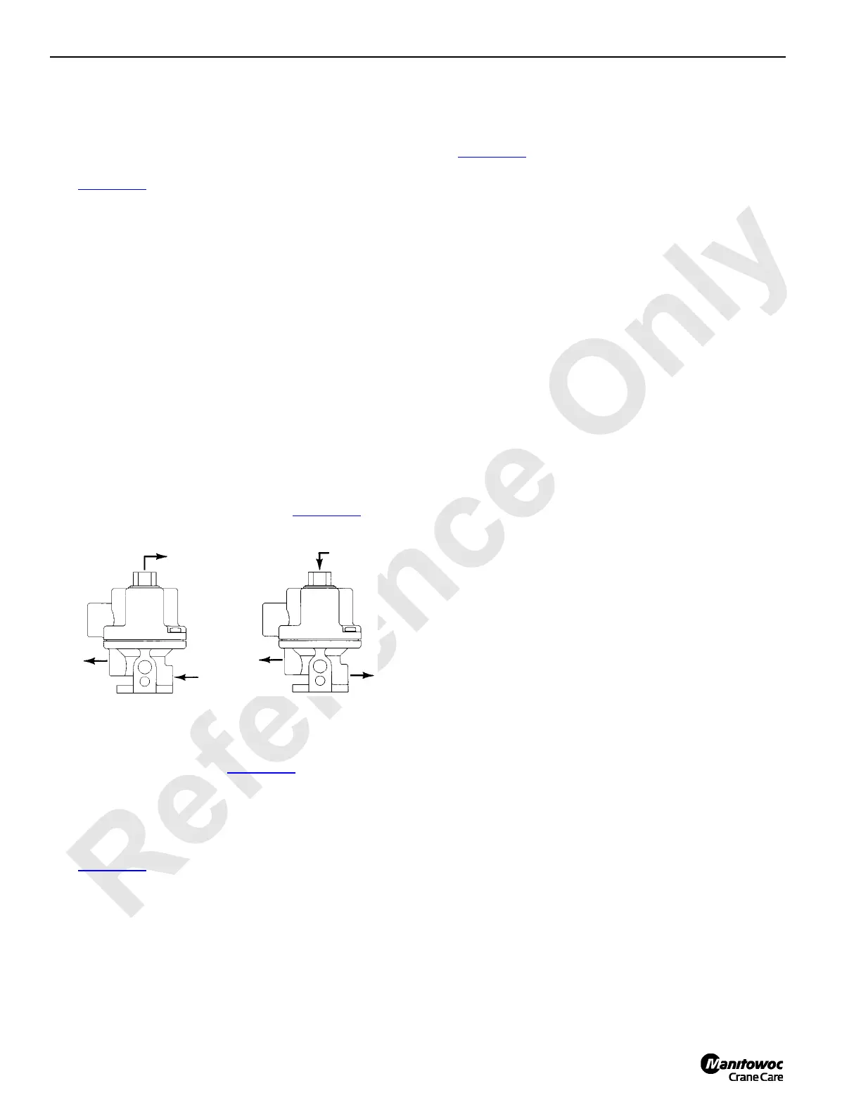
FIGURE 2-39
“P”
“A”
“E”
Normally Closed
S126 “P”
“A”
S125
Normally Open
“E”

 Loading...


