Manitowoc Published 11-06-15, Control # 040-13 1-37
2250 SERVICE/MAINTENANCE MANUAL INTRODUCTION
When a control handle is moved from off, an input voltage in
the handle command direction is sent to the PC. The PC
does not release selected brake until pressure memory
holding pressure is reached to hold the load, as determined
by the system pressure sender.
When hydraulic brake solenoid is enabled, selected brake
valve shifts to block tank port and to supply pilot pressure
from boom/luffing jib charge pump to release selected brake.
When a brake solenoid is disabled, the solenoid valve closes
to block charge pump port and to vent brake pressure to
tank. The spring brake applies. If brake pressure or electrical
power is lost when operating, brakes apply.
Load Drum Air Brakes
See Figure 1-20 for the following procedure.
Each load drum brake has two air cylinders, and each
cylinder has two chambers. The first brake cylinder chamber
is a spring-applied/air-released brake controlled by the PC.
The other part of the first cylinder chamber is a working brake
for free fall that is air-applied/spring-released. The second
brake cylinder chamber is a spring-applied/air-released
brake controlled by the PC and the other brake cylinder
chamber is not used.
Release the load drum brakes by placing selected load drum
brake switch in off position. The PC enables the brake
solenoid when load pressure memory is reached.
When the PC enables Drum 1, 2 or 3 load drum brake
solenoid (AS-7, AS-9, or AS-11), regulated air shifts brake
relay. This allows manifold air to close quick release valves.
Air flows to brake cylinder chambers, compressing the
springs to release brake. With selected load drum brake
released, load drum motor can hold the load when operating
in full-power operation.
In Standard mode when the selected load drum control
handle is in off position or selected load drum brake switch is
in off position, brakes are spring-applied. Air in brake
cylinders is exhausted to ensure that load drum brake spring
applies. Exhausted air from brake cylinders goes through
quick release valves when sealing pressure is exhausted off
the valve diaphragms, opening exhaust ports. This occurs
when pilot pressure is removed from brake relay valve.
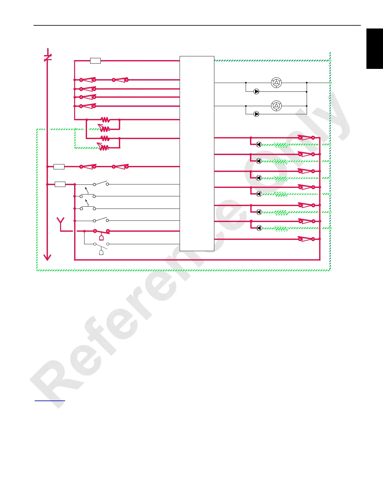
0
0
K1
F10
8
8D
LIMIT BYPASS
WB-25
87FA 87F
MAXIMUM ANGLE LIMIT
MAX. WORKING ANGLE LIMIT
BLOCK UP LIMIT WB-06
WB-17
WA-35
LIMIT SWITCH
EQUALIZER
LIMIT SWITCH
BOOM STOP
8M
WD-13
UPPER
MAIN
LOWER
MAIN
REGULATED 10V DC OUT
RF-11
5A
SYSTEM FAULT ALARM
WC-34
WC-35
OPERATING LIMIT ALARM
LIGHT
5A
WB-10
SEAT SWITCH
WB-22
LEFT REAR DRUM
MINIMUM BAIL LIMIT DRUM 1
WB-03
WB-14
BOOM UP LIMIT
MAXIMUM BAIL LIMIT DRUM 1
WB-02
MINIMUM BAIL LIMIT DRUM 2
WB-08
MAXIMUM BAIL LIMIT DRUM 2
WB-07
LIGHT
LUFFING JIB LIMIT BYPASS
WE-14
ENGINE OIL PRESSURE
WD-08
ENGINE COOLANT TEMP.
WD-09
3
8D
MINIMUM BAIL LIMIT DRUM 3
WB-04
MAXIMUM BAIL LIMIT DRUM 3
WB-05
F7
WA-17
WA-18
HYDRAULIC FLUID TEMP.
HYDRAULIC FLUID LEVEL
MINIMUM ANGLE LIMIT
WB-16
3A
10A
CONTROLLER
PROGRAMMABLE
FIGURE 1-19
 Loading...


