Manitowoc Published 11-06-15, Control # 040-13 5-13
2250 SERVICE/MAINTENANCE MANUAL HOISTS
b. Connect a 0 to 150 psi (0 to 10,3 bar) air pressure
gauge to out port between valve and actuator.
c. Depress pedal so it is approximately 1/32 in (0,8
mm) from touching bumper. Gauge should read 115
to 125 psi (7,9 to 8,6 bar).
Do not set pressure higher than 125 psi (8,6 bar).
d. If required, loosen jam nut (7) and tighten set screw
(8) to increase pressure. Loosen set screw to
decrease pressure. Securely tighten jam nut to lock
adjustment.
e. Release brake pedal to fully raised position; gauge
should read 0 psi (0 bar). If required, loosen jam nut
(9) and turn screw (10) in until pressure is 0 psi (0
bar). Securely tighten jam nut to lock adjustment.
f. Remove gauge.
g. Repair or replace valve if correct pressures cannot
be obtained.
Brake Actuator Overhaul
Removal
See Figure 5-7 for the following procedure.
1. Read precautionary steps given after heading.
2. Lower load block, weight ball, or bucket to ground from
drum being serviced so wire rope is slack.
3. If equipped with three drums, use drum selector to select
desired rear drum, right or left.
4. Fully release drum working brake (brake pedal up fully).
5. Turn on free-fall and turn off drum park for drum being
serviced. Drum parking brake will release.
6. Cage power spring in actuator, as follows:
Current Production:
a. Using a 3/4 in (19 mm) deep-socket wrench, turn
release bolt counter-clockwise 22 to 23 turns.
Past Production:
a. Unsnap dust cap from top of actuator.
Using a 3/4 in (19 mm) deep-socket wrench, turn
release bolt counter-clockwise until bolt and washer are
completely removed.
7. Stand clear of actuator. Turn on drum park for drum
being serviced. Parking brake will spring apply. Piston
rod may extend slightly when this step is performed.
8. Tag air lines for proper identification when reinstalling
actuator; then disconnect air lines from actuator.
9. Remove rod end pin to disconnect rod end from brake
lever.
10. Remove mounting nuts and remove actuator from
support. Actuator weighs approximately 30 lb (14 kg).
Repair
Follow instructions in manufacturer’s service manual to
properly repair actuator.
Rework – Current Production Actuators
See Figure 5-10 for the following procedure.
Before installing a new or rebuilt actuator, rework it according
to the following steps:
1. Remove jam nut from piston rod end.
2. Turn spring brake release bolt clockwise until tight and
torque to 74 ft-lb (100 N•m).
3. Apply at least 90 psi (6,2 bar) air pressure to spring
brake port of actuator.
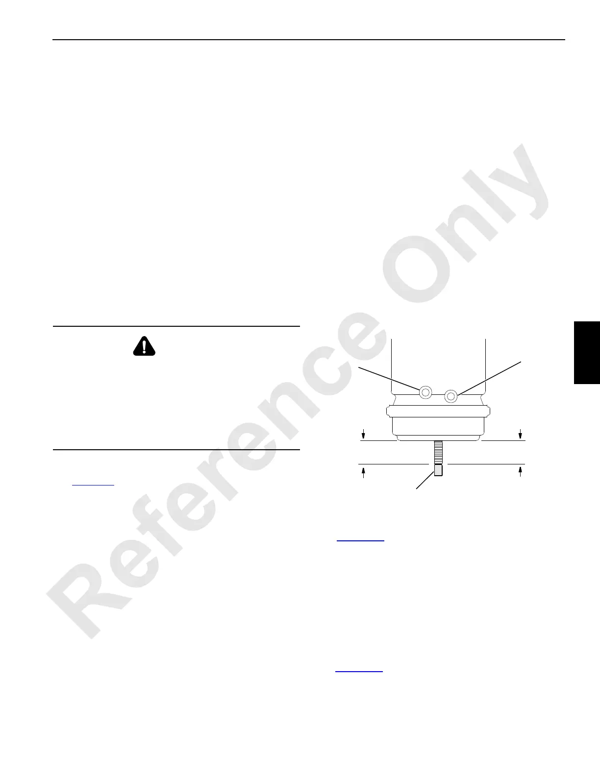
4. Cut off piston rod at 1-7/8 in (48 mm) as shown in
Figure 5-10
for standard actuators and 1-1/2 in (38 mm)
for clamshell drum actuators.
WARNING
Personnel Injury Hazard!
Actuator is spring loaded; do not attempt to disassemble
actuator while it is on crane. Remove actuator according
to the following instructions.
See instructions in manufacturer’s service manual for
proper disassembly of actuator. Otherwise, actuator will
fly apart with dangerous force.
FIGURE 5-10
1-7/8 in (48 mm)
(Split Rear)
A467
Cut Off Excess
Piston Rod
Spring Brake Port
(Parking Brake)
Service Brake Port
(Working Brake)
1- 1/2 in (38 mm)
(Full Front/Rear)
NOTE: Mounting studs
removed for clarity.

 Loading...


