INTRODUCTION 2250 SERVICE/MAINTENANCE MANUAL
1-24
Published 11-06-15, Control # 040-13
CRANE DESCRIPTION OF OPERATION
General Operation
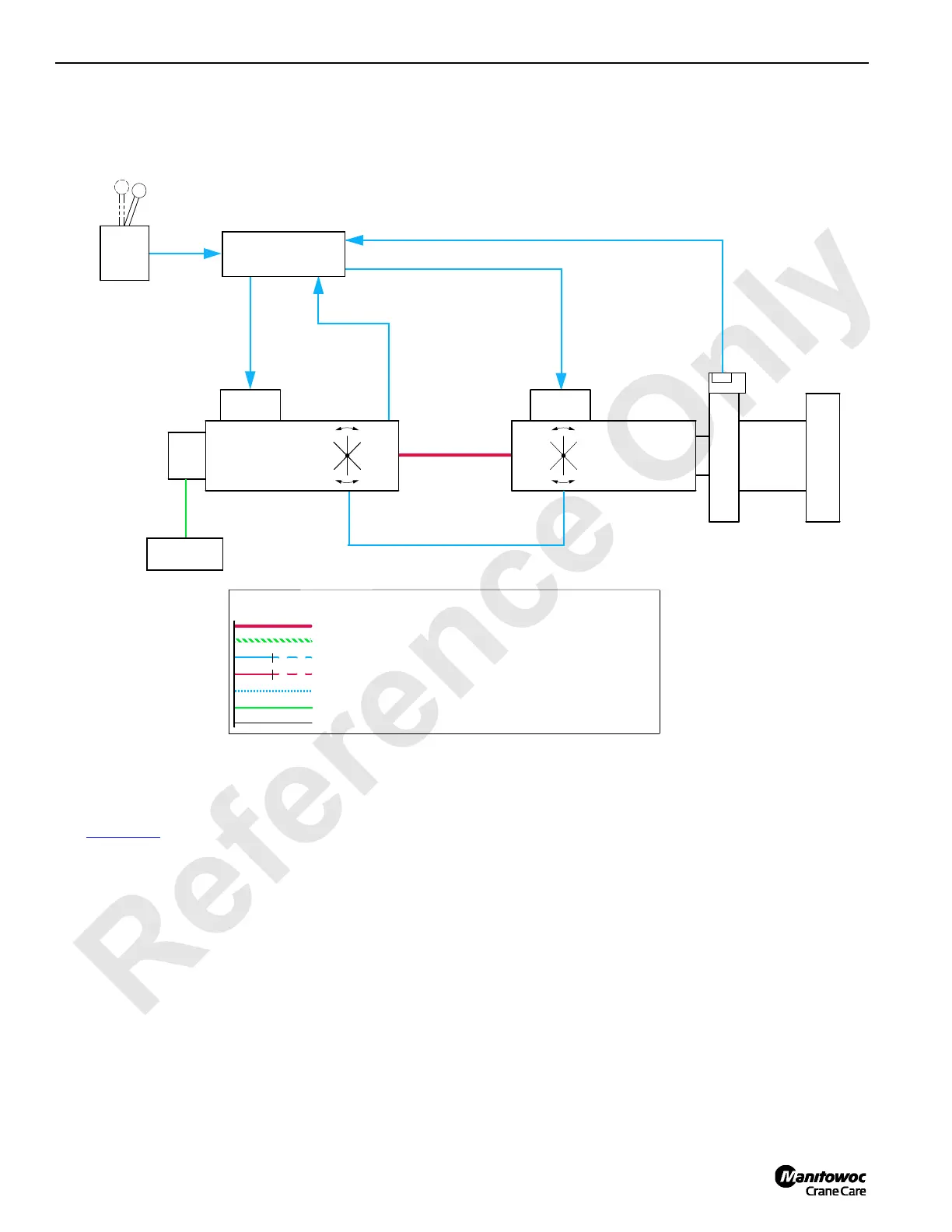
See Figure 1-10 for the following procedure.
This section describes the model 2250 powered with the
Cummins QSX15 or the Caterpillar 3406C engine. Standard
and optional equipment available for the crane is included.
Disregard any equipment your crane does not have. See the
MAX-ER™ 2000 Operator Manual for information on the
MAX-ER 2000. See MAX-ER 2000 Description of Operation
topic in this section.
The Model 2250 operating system is an EPIC
(Electrical
Processed Independent Control). Through the PC
(Programmable Controller) the independently powered
pumps, motors, and cylinders provide controller driven
control logic, pump control, motor control, on-board
diagnostics, and service information. Crane information is
displayed on digital display screen in operator’s cab.
A single diesel engine provides power to operate system
pumps through a pump drive transmission. In a closed-loop
hydraulic system, high-pressure hydraulic fluid from the
system pump drives a hydraulic motor. Pressure develops
within the closed-loop system while resistance to movement
of the load on motor is overcome. When movement begins,
pump volume displacement maintains motor speed. The
spent hydraulic fluid from motor outlet returns directly to
pump input. The crane closed loop systems are swing, right
travel, left travel, boom hoist, load drums, and luffing jib hoist.
COMMAND
SIGNAL
PILOT
CONTROL
PRESSURE
PCP
EDC
LINE LEGEND (FOR ALL SCHEMATICS)
CASE RETURN PRESSURE HYDRAULIC
CONTROL OR PILOT PRESSURE HYDRAULIC, REGULATED AIR
LOW-PRESSURE HYDRAULIC, SIGNAL ELECTRICAL, EXHAUSTED AIR
NEGATIVE ELECTRICAL (GROUND)
HIGH-PRESSURE HYDRAULIC, POSITIVE ELECTRICAL, MANIFOLD AIR
POSITION
SWASHPLATE
HIGH-PRESSURE SIDE
MOTOR
HYDRAULIC
PUMP
HYDRAULIC
DRUM
CONTROLLER (PC)
MANIFOLD
SUCTION
PUMP
CHARGE
LOW-PRESSURE SIDE
FEEDBACK
FEEDBACK
PRESSURE
(MOTOR STROKE)
CONTROL SIGNAL
(PUMP STROKE)
CONTROL SIGNAL
CONTROL
DISPLACEMENT
ELECTRONIC
HANDLE
CONTROL
PIPING
HYDRAULIC
PROGRAMMABLE
HANDLE
RF-01
HYDRAULIC SUCTION MANIFOLD LINE
NOT ACTIVE LINE OR CIRCUIT
SPEED SENSOR
FIGURE 1-10
 Loading...


