HOISTS 2250 SERVICE/MAINTENANCE MANUAL
5-12
Published 11-06-15, Control # 040-13
- Readjust brake when 2-1/16 in (52 mm) is
reached.
g. If proper dimension is not obtained, turn off drum
park to release brake for drum being serviced.
h. Tighten band adjusting nut one to two flats at a time.
i. Repeat step 6f
until proper dimension is obtained.
j. Turn off drum park for drum being serviced. Drum
parking brake will release.
k. Check for clearance between brake lining and drum
flange:
- Grasp brake band at band adjusting nut. Band
should move back and forth freely by hand.
- As a further check, drum should turn freely
when load line is pulled by hand (clutch and
parking brake released). If drum does not turn
freely by hand and band is loose, clutch may
not be releasing. See Drum Clutch Inspection
and Adjustment topic in this section.
- If necessary, loosen jam nut at band supports
(Figure 5-7
). Turn adjusting nuts in required
direction to provide clearance between lining
and drum flange. Securely tighten jam nuts to
lock adjustment.
l. For independent drum drive, repeat steps 6d
through 6k for brake on opposite side.
Dimension measured in step 6f
must be identical for
each brake on drum to provide balanced braking.
7. Band adjustment is now complete. Select and confirm
desired operating mode.
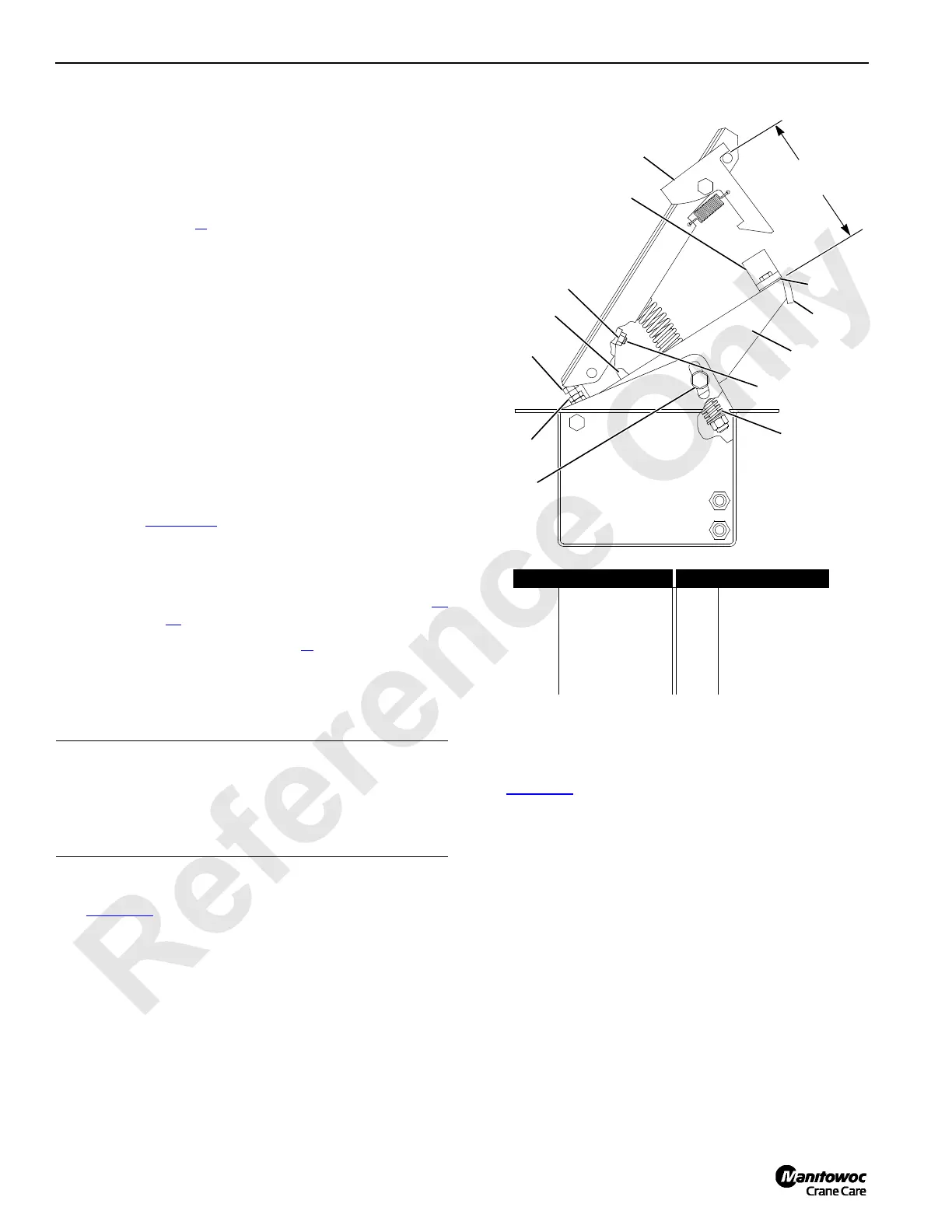
Treadle Valve Checks
See Figure 5-9 for the following procedure.
1. Check each pedal latch and latch bar for wear. Pedal
latch must hold pedal down in fully applied position.
2. Connect 0 to150 psi (0 to 10,3 bar) air pressure gauge to
in and out ports of valve:
• Air pressure at in port should be 120 to 132 psi (8,3
to 9,1 bar).
• Air pressure at out port should modulate from 0 to
75 psi (0 to 5,2 bar) as pedal is slowly depressed
and then go to 120 to 132 psi (8,3 to 9,1 bar).
Treadle Valve Adjustments
See Figure 5-9 for the following procedure.
1. Lower load for treadle valve being adjusted to
ground so load line is slack.
2. Adjust pedal to desired height:
a. Latch pedal down.
b. Loosen four cap screws (1).
c. Move valve support (2) to desired height.
d. Securely tighten cap screws.
3. Adjust spring (3) for a 2-7/8 in (73 mm) preload.
4. Install shims (4) under bumper (5) so pedal compresses
bumper 1/32 in (0,8 mm) when pedal is latched.
5. Adjust valve (6) as follows:
a. Release brake pedal to fully raised position.
CAUTION
Drum Flange Damage!
Brake lining must not rub against drum flange when brake
is released. Otherwise, lining will overheat, possibly
resulting in cracks in drum flange.
FIGURE 5-9
5-1/4 in
(133 mm)
IN
OUT
B225
Item Description Item Description
1 Cap Screw 7 Jam Nut
2 Valve Support 8 Set Screw
3Spring 9Jam Nut
4Shims 10Screw
5 Bumper 11 Pedal Latch
6 Valve 12 Latch Bar
1
2
3
4
5
6
7
8
9
10
11
12
 Loading...


