POWER TRAIN 2250 SERVICE/MAINTENANCE MANUAL
7-14
Published 11-06-15, Control # 040-13
5. Clean all dirt and other debris from outside of radiator.
6. Check that overflow line on auxiliary tank is open.
7. Drain and refill cooling system, as follows:
a. Raise gantry to raise auxiliary tank.
b. Stop engine.
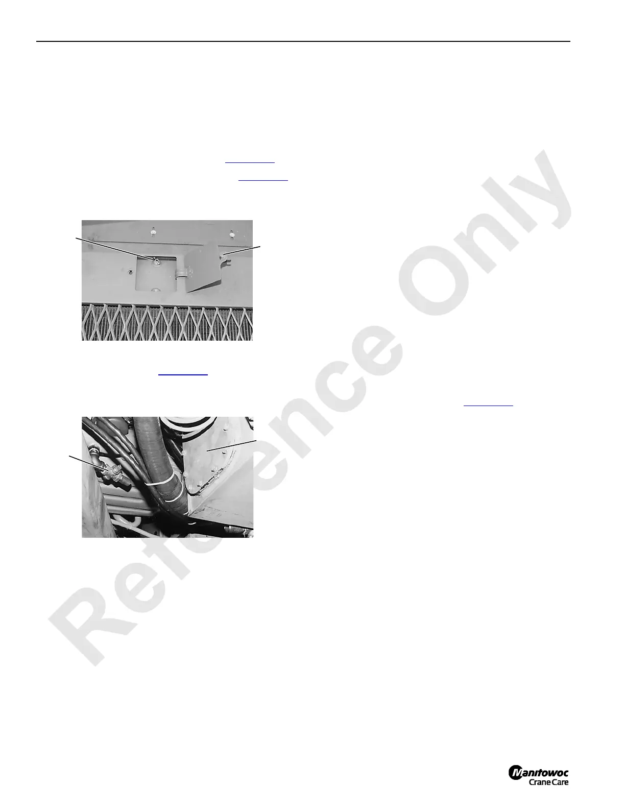
c. Remove fill cap from auxiliary tank (Figure 7-14
).
d. Open petcock at both ends of radiator (Figure 7-14
).
e. Open drain valve (Figure 7-15
) and drain coolant
into suitable container.
f. Close drain valve once system is completely
drained.
g. Fill cooling system through auxiliary tank to middle
of full level cold gauge or to bottom of fill neck.
Close petcocks on radiator once clear coolant
appears.
See Lubrication Guide in Section 9 of this manual
for cooling system capacity.
See engine manufacturer’s manual for antifreeze
and coolant additive recommendations.
h. Install fill cap and run engine at high idle until engine
is hot — approximately 197°F (92°C).
Look for coolant leaks while engine is running;
correct if found.
i. Stop engine, wait until engine is cool, and refill
auxiliary tank to proper level.
ENGINE COOLING SYSTEM WITH CUMMINS
QSX-15 ENGINE — CURRENT TIER 3
General
The cooling system consists of a horizontal radiator
(mounted above engine) and a hydraulically driven blower-
type fan.
Cooling System Operation
Cooling system flow is illustrated in Figure 7-16.
The cooling system is of the deaeration type, which
continually removes air from the system, as follows:
• A small percentage of total coolant flow is circulated
through vent line to radiator.
• Since coolant circulation is very slow in radiator, air
separates from coolant.
• Air collects at top of radiator. When pressure rises to 14
psi (0,97 bar), relief in fill cap opens to exhaust air
through overflow line.
• Deaerated coolant returns to system through make-up
line.
FIGURE 7-14
P782
Petcock
Cover
Typical Both Ends of Radiator
FIGURE 7-15
P784
Hydraulic
Tank
Drain
Valve
View Under Rear of Engine

 Loading...


