Manitowoc Published 11-06-15, Control # 040-13 1-69
2250 SERVICE/MAINTENANCE MANUAL INTRODUCTION
Crawler Frame Pins
See Figure 1-37 and Figure 1-41 for the following procedure.
The following description is for engaging/disengaging of the
left crawler frame pins. Operation of the right crawler frame
pins is the same as the left crawler frame pins.
Power is available to setup remote control when the cable is
connected at air valve junction box on left side of rotating bed
and engine is running.
Crawler Frame Pins Engage
When power button is pressed and left crawler frame pins
switch is held in the down engage position, an input signal is
sent to the PC. The PC sends a 12 volt output signal to
auxiliary system disable relief valve HS-12 that adjusts
system pressure to 3,500 psi (241 bar).
The left crawler frame pins solenoid HS-2 is enabled by the
PC to shift the solenoid valve in the engage position.
Hydraulic fluid enters upper accessory valve and flows
through variable output control valve HS-20 and hydraulic
quick disconnect to lower accessory valve.
Hydraulic fluid exits the valve assembly and flows to piston
end of left crawler frame pin cylinders, engaging the
cylinders, to connect left crawler frame with crawler frame.
Fluid from rod end of cylinders flows back through valve
assembly through hydraulic quick disconnect and to tank.
When power button or left crawler frame pins switch is
released, the PC sends a 0 volt output to shift spool of
solenoid HS-2 to center position.
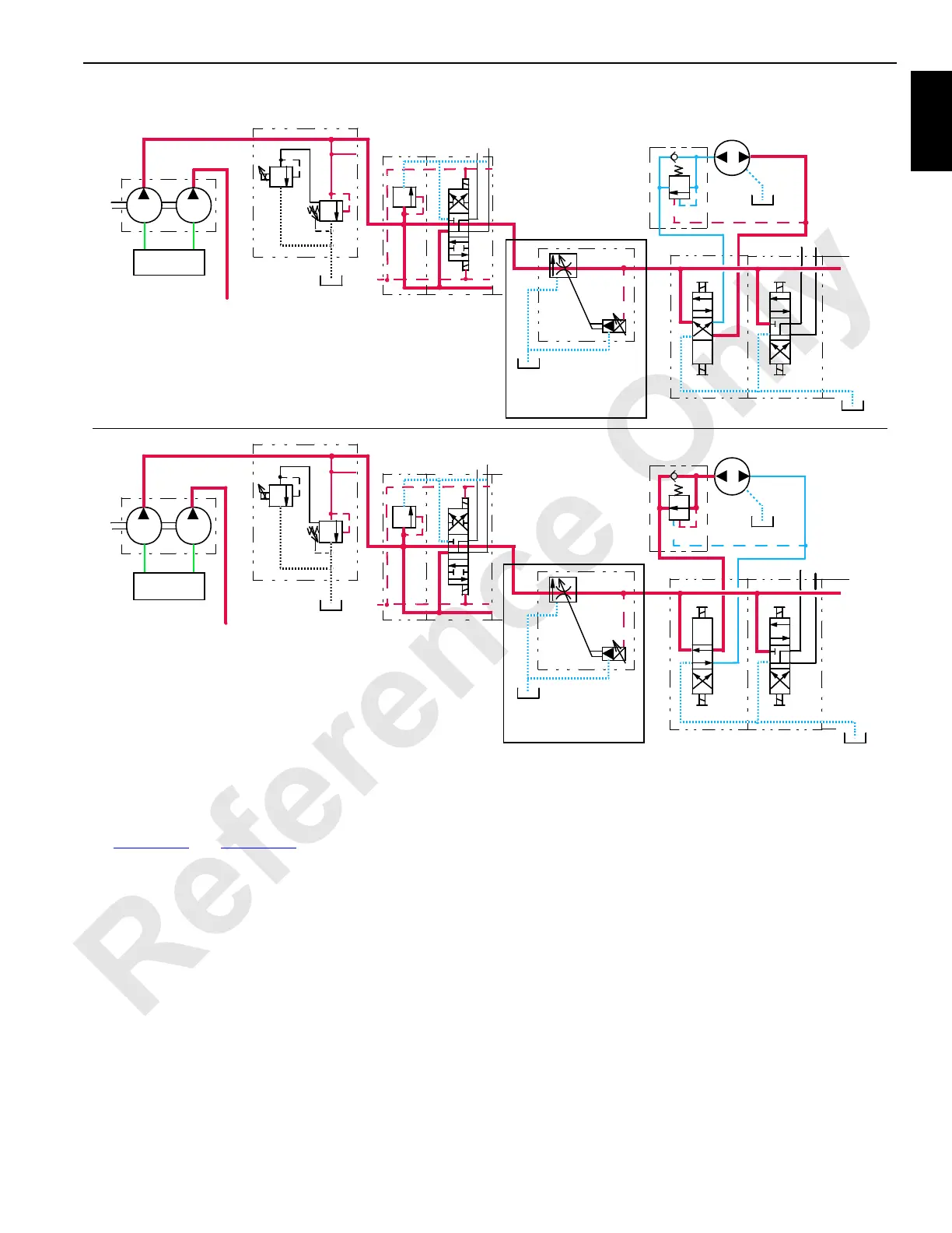
RF-38
RIGGING WINCH HAUL IN
RIGGING WINCH PAY OUT
RF-37
AUXILIARY SYSTEM
RELIEF VALVE
HS-12
AUXILIARY PUMP
FAN PUMP
TO FAN
DISABLE
CIRCUIT
UPPER ACCESSORY VALVE
HS-17
HS-18
LOWER ACCESSORY VALVE
x
VARIABLE OUTPUT VALVE
0 TO 15 gpm (57 l/min)
AUXILIARY SYSTEM
SUCTION
MANIFOLD
RELIEF VALVE
HS-12
AUXILIARY PUMP
FAN PUMP
TO FAN
DISABLE
CIRCUIT
UPPER ACCESSORY VALVE
HS-17
HS-18
LOWER ACCESSORY VALVE
x
VARIABLE OUTPUT VALVE
0 TO 15 gpm (57 l/min)
SUCTION
MANIFOLD
X
X
FIGURE 1-40
(PAST PRODUCTION)
(PAST PRODUCTION)
 Loading...


