INTRODUCTION 2250 SERVICE/MAINTENANCE MANUAL
1-46
Published 11-06-15, Control # 040-13
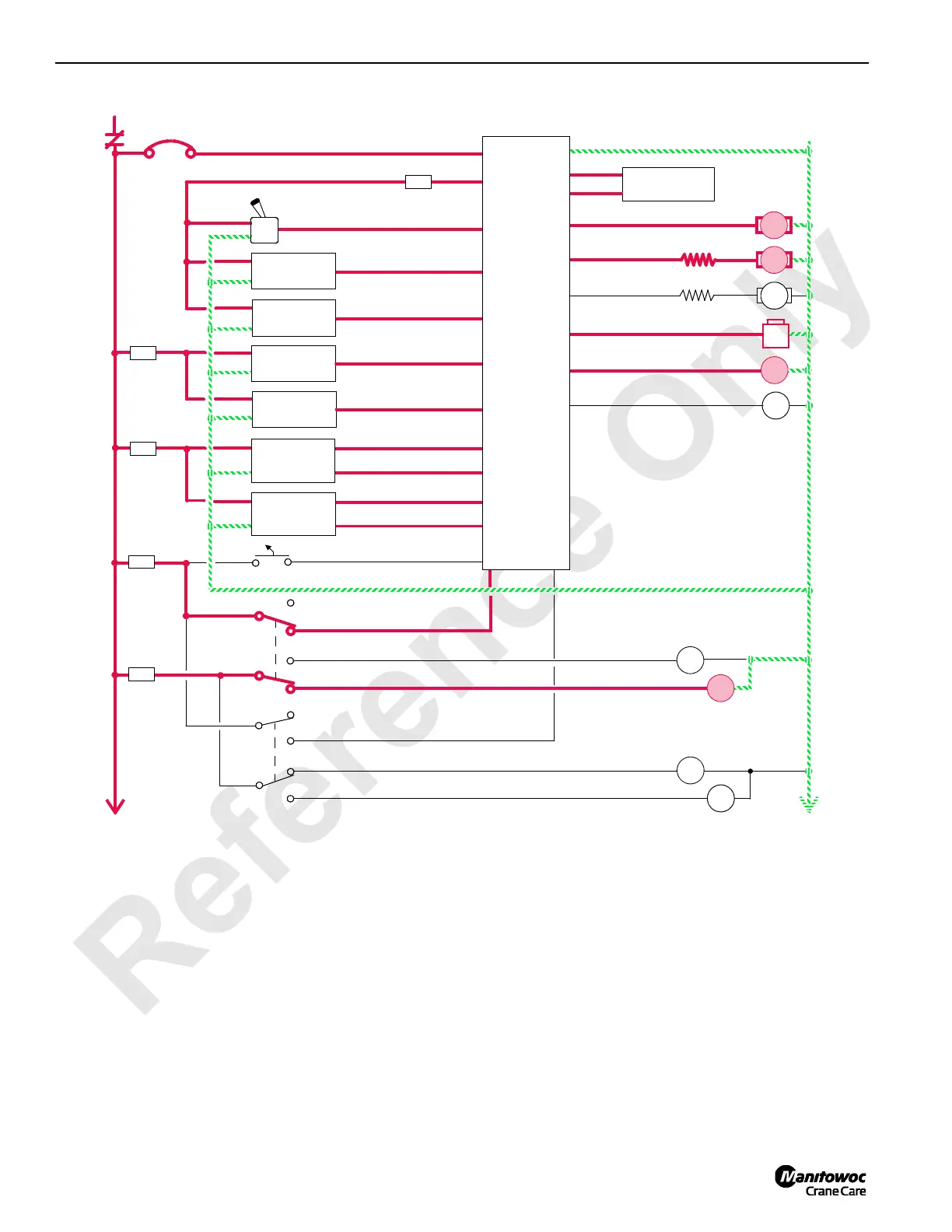
Boom Hoist/Luffing Jib Lower
The following description is for the boom hoist system. The
luffing jib system is similar.
When control handle is moved forward for booming down,
an input voltage of 5 volts or less is sent to the PC. The PC
sends a variable plus 0 to 2.8 volt output that is applied to
pump EDC. The PC sends a variable 0 to 2.19 volt output
that is applied to motor PCP. The PC checks that all block up
limit switches are closed and that a system fault is not
present.
The pump EDC tilts swashplate up to satisfy pressure
memory. The PC compares boom hoist-holding pressure to
value in pressure memory. When system pressure is high
enough, the PC sends a 12 volt output to brake solenoid
valve HS-6. The brake solenoid shifts to block drain port and
opens port to pilot pressure from boom hoist charge pump to
release drum brake. When brake is released, pump EDC
continues to tilt swashplate down. Hydraulic fluid flow is from
pump outlet port to motor inlet port. Return fluid is from motor
outlet port to pump inlet port.
The PC output voltage to pump EDC and the PC output
voltage to motor PCP is relative to control handle movement.
As control handle is pushed forward, pump swashplate angle
is increased. When system pressure exceeds the PCOR
(Pressure Compensating Over-Ride) valve setting of 4,930
psi (340 bar), the valve shifts to direct flow from shuttle valve
into maximum displacement side of servo cylinder.
RF-17
50 AMP
8P1
10 VDC REGULATED SUPPLY
WA-05
WA-01
LEFT SIDE CONTROL HANDLE
K1
8
RAISE
5A
F16
3A
LOWER
F12
5A
8T
CRANE DISPLAY
WD-19
WD-20
WC-14
BOOM HOIST PUMP
EDC
B
A
0
GND
BOOM HOIST
PRESSURE
SENDER
WA-26
WA-20
WD-06
WD-05
BOOM HOIST
SPEED
SENDER
F
A
B
D
(DRUM 4)
HS
6
BOOM ANGLE
INDICATOR
87FA
WD-27
ROTATION INDICATOR
BOOM HOIST BRAKE
AS
14
AS
13
F8
15A
8S
WB-29
BOOM HOIST PAWL IN
BOOM HOIST PAWL OUT
BOOM HOIST BRAKE
WC-09
5A
8E
WE-29
BOOM HOIST MOTOR
PCP
B
A
WD-24
LUFFING JIB MOTOR
PCP
B
A
HS
19
LUFFING JIB BRAKE
WC-25
AS
16
AS
15
LUFFING JIB PAWL IN
LUFFING JIB PAWL OUT
LUFFING JIB BRAKE
WB-30
WA-21
LUFF. JIB ANGLE
INDICATOR
LUFFING JIB
PRESSURE
SENDER
WA-19
WD-02
WD-01
LUFFING JIB
SPEED
SENDER
F
A
B
D
(DRUM 5)
F11
F10
5A
8D
WE-14MAX. BOOM/LUFFING ANGLE
PROGRAMMABLE
CONTROLLER
FIGURE 1-25
 Loading...


