Manitowoc Published 11-06-15, Control # 040-13 1-47
2250 SERVICE/MAINTENANCE MANUAL INTRODUCTION
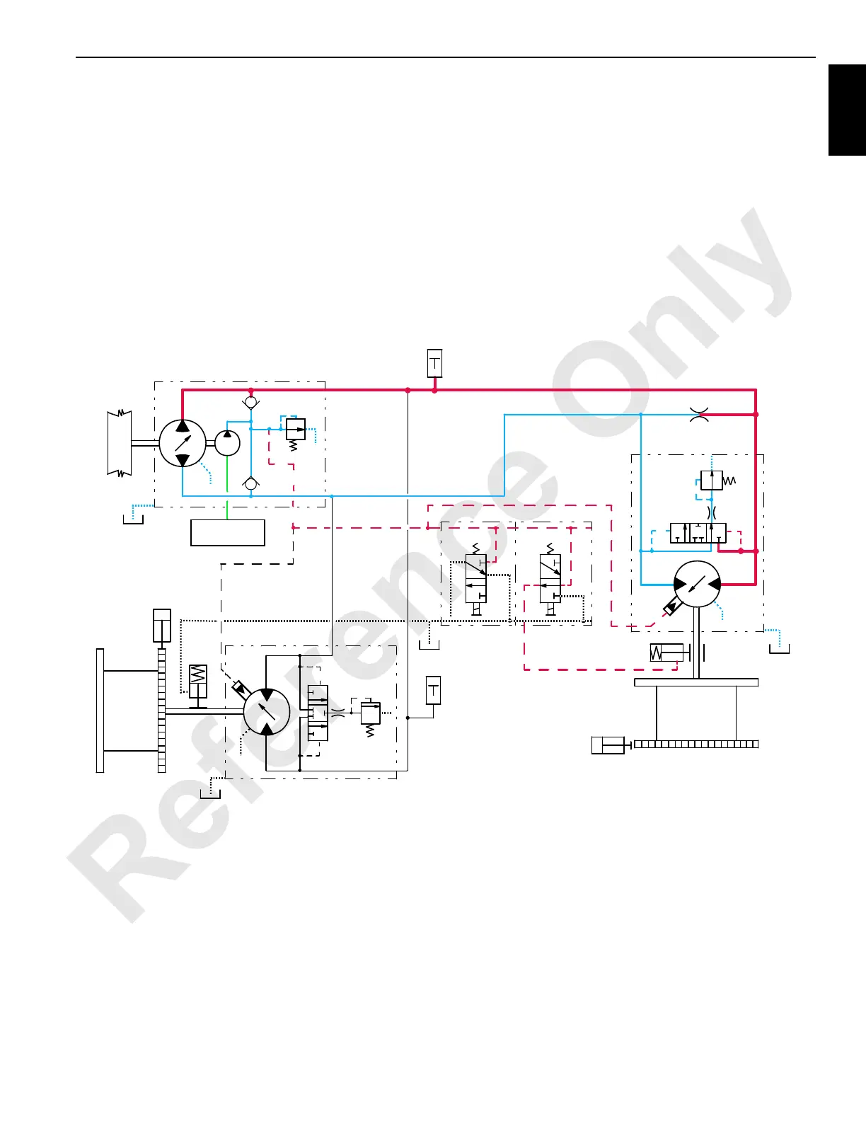
The PCOR valve over-rides the command from servo PC
valve, increasing motor displacement and output torque and
reducing output speed. When PCOR valve closes, control of
the motor returns to servo PC valve.
The PC is continuously balancing the system pressure and
the motor displacement angle so the motor displacement
goes to minimum when control handle is fully forward, if the
motor torque is not too high. The PC monitors motor
displacement and controls motor speed by regulating the
hydraulic fluid flow through the pump.
The weight of boom attempts to drive motor faster than
return fluid can return to low-pressure side of pump. System
charge pump maintains fluid supply at a positive pressure to
motor. Pump swashplate position restricts the returning fluid
flow. Pressure builds on fluid return side of closed-loop,
acting as a hydraulic brake to control lowering speed.
When boom hoist control handle is moved toward neutral
position, the PC compensates for hydraulic system leakage
or changing engine speed. The PC sends a 0 volt output to
pump EDC that moves swashplate to center position. This
shifts the motors back to maximum displacement for slower
output speed to slow the drum rotation.
The PC stores the boom holding pressure in pressure
memory. After control handle center switch opens, The PC
sends a 0 volt output to disable brake solenoid valve HS-6.
Drum brake solenoid valve shifts to block boom hoist charge
pump pilot pressure to brakes and opens a line to tank.
Brake applies before drum pump de-strokes.
HS-6
RF-18
DRUM
SUCTION
MANIFOLD
DOWN
UP
340 PSI
(23 BAR)
A
B
BOOM HOIST/LUFFING JIB PUMP
.060
PILOT
BOOM HOIST
BRAKE
A
275 PSI
(19 BAR)
B
AIR PAWL
CYLINDER
PRESSURE
SENDER
HS-19
DRUM
BRAKE
A
277 PSI
(19 BAR)
B
SERVO
LUFFING
JIB
AIR PAWL
CYLINDER
(SEE FIGURE 18)
PRESSURE
LUFFING JIB MOTOR
BOOM HOIST MOTOR
DOWN
UP
PRESSURE
SENDER
SERVO
FIGURE 1-26
 Loading...


