INTRODUCTION 2250 SERVICE/MAINTENANCE MANUAL
1-92
Published 11-06-15, Control # 040-13
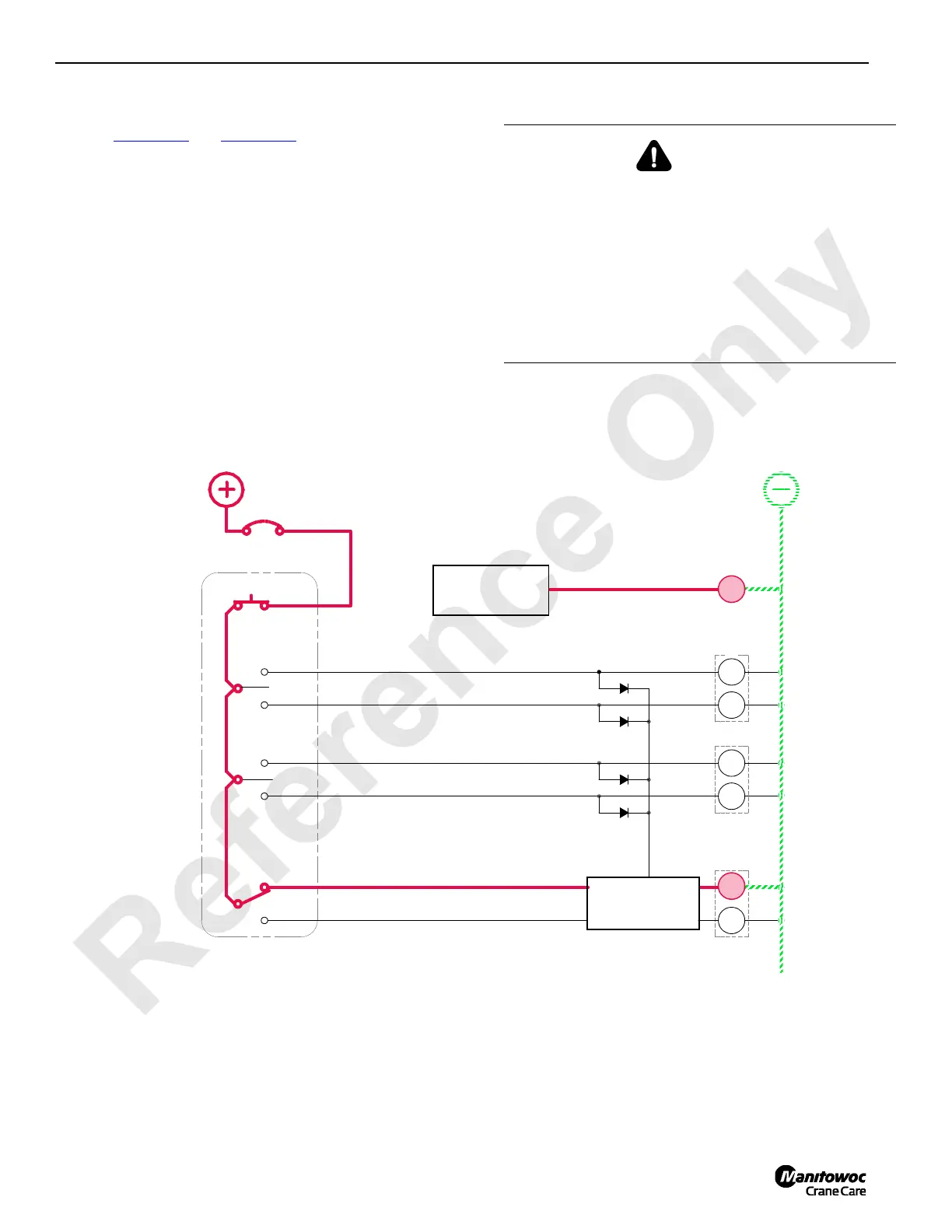
Counterweight Strap Cylinders
See Figure 1-58 and Figure 1-59 for the following procedure.
When the MAX-ER mode is selected, the load sensing pin in
the gantry left side back hitch measures loading created by
the lifted load. The load-sensing pin sends a proportional 0.8
to 8.0 volts signal to the crane PC. The crane PC converts
the load-sensing pin voltage signal to U.S tons that is
displayed on MAX-ER (MXR) screen.
The counterweight strap cylinders automatically lift the
wheeled counterweight assembly off the ground and sets it
back down when required depending on load (governed by
boom angle, boom length, lifted load). When the wheeled
counterweight assembly is off the ground, the crane can
swing and travel in the normal manner to position the crane
and load. When the wheeled counterweight assembly is on
the ground, the wheels must be properly positioned before
swinging or traveling the crane.
DANGER
Collapsing Mast!
After straps are pinned to strap cylinders, do not manually
retract cylinders. Mast can be pulled over backwards.
Strap cylinders automatically adjust when MAX-ER mode
is selected.
Tipping Hazard!
Counterweight switch can be used to extend mast strap
cylinders manually if load-sensing pin fails. Any other use
of this control is neither intended nor approved.
56MB
56MA
90L
90k
POWER
HS
43
HS
52
HS
53
HS
89J4
89K4
0
15 AMP
CB
5A
8K
RM-13
SWING/CRAB (STEERING CYLINDER EXTEND
STEERING PINS EXTEND
STEERING PINS RETRACT
COUNTERWEIGHT STRAP
CYLINDER EXTEND
COUNTERWEIGHT STRAP
CYLINDER RETRACT
MAX-ER 2000 REMOTE
12
HS
HS
42
SWING/CRAB (STEERING CYLINDER RETRACT
HS
40
41
FIGURE 1-58
89H4
MAX-ER 2000
PROGRAMMABLE
CONTROLLER
AUXILIARY SYSTEM
DISABLE VALVE
CRANE
PROGRAMMABLE
CONTROLLER
88S
 Loading...


