HYDRAULIC AND AIR SYSTEMS 2250 SERVICE/MAINTENANCE MANUAL
2-28
Published 11-06-15, Control # 040-13
4. Wash all parts in soap and water and dry.
5. For the Type A filter, wash the element in alcohol and
blow it out from the inside with air. For the Type B filter,
discard the element.
6. Inspect all parts for damage and replace as necessary.
7. See Figure 2-31
and reassemble the filter. Tighten all
threaded parts securely.
8. If disconnected, reconnect the air lines to the proper
ports of the filter. Use pipe-thread sealant or tape
sparingly and apply only to the male threads.
NOTE: The top of the Type A filter is marked in and out to
identify the ports. Connect the line from the tank to
the in port.
The top of the Type B filter has an arrow to identify
direction of flow. The arrow must point away from
the air tank.
9. Close all drain valves and open all shut-off valves.
10. Build air system pressure to the normal operating range
and check the filter for leaks.
Automatic Drain Valve Operation
NOTE: The automatic drain valve is not used on all filter
installations.
The automatic drain valve contains a float. When the liquid in
the valve body rises to the level of the float, the float rises to
open a needle valve. This action allows the liquid to drain. Air
pressure then re-seats the float, and the cycle repeats.
AIR SYSTEM DE-ICER MAINTENANCE
Operation
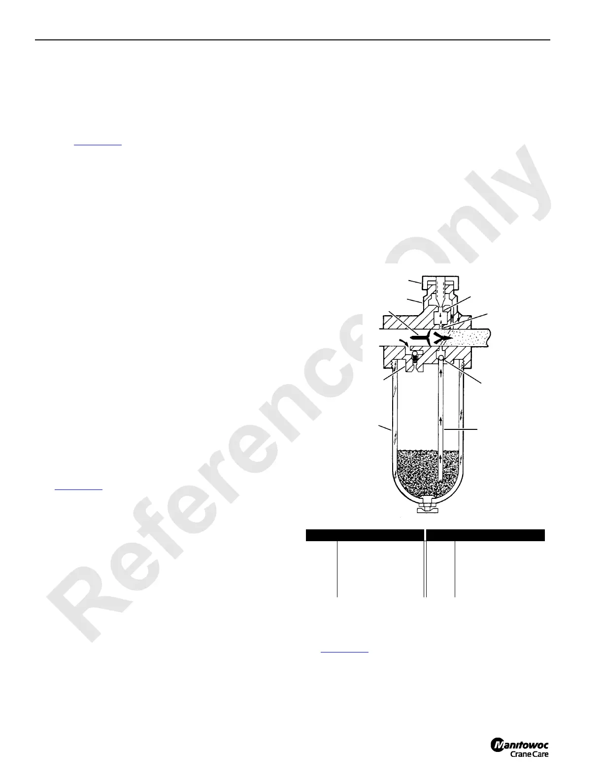
See Figure 2-32 for the following procedure.
Air system de-icer meters anti-freeze into the air line only
when there is air flow through the de-icer. Air flowing through
the de-icer passes around flow sensor (1) to the downstream
system. Inlet pressure is admitted to the reservoir through
check (charge) valve (2). When air is flowing, a small
pressure drop occurs across the flow sensor. The outlet
(lower) pressure is sensed in sight feed dome (3) through
nozzle passage (4). This establishes a pressure drop across
metering orifice (5) and anti-freeze at inlet pressure flows
upward through siphon tube (6) into the sight feed dome
where it drips into the nozzle passage and then into the de-
icer throat. Adjusting knob (7) controls the drip rate. Anti-
freeze drops are atomized by the high velocity air flowing
past the flow sensor and are carried downstream. Check ball
(8) prevents back flow of anti-freeze into the reservoir during
periods of no flow.
Flow sensor functions as a variable restriction in the throat of
the de-icer to produce a pressure drop of up to 5 psi (0,3 bar)
that is proportional to the rate of air flow through the de-icer.
These variations in outlet pressure, sensed in the sight-feed
dome, cause a like variation in the pressure drop across the
metering orifice as a function of air flow. Thus, for a given
drip rate setting at some average air flow, a lower air flow will
cause a proportionally higher drip rate.
Charge valve (2) controls the rate of reservoir pressurization
and allows rapid de-pressurization for refilling without
shutting off the air pressure. When anti-freeze plug is
loosened, a bleed orifice is exposed which immediately
reduces the reservoir pressure. This pressure drop causes
the charge valve to close and restrict air flow into the
reservoir to eliminate blow-back when adding anti-freeze.
When the fill plug is replaced, the reservoir re-pressurizes
through the charge valve at a nominal rate. The charge valve
opens fully when inlet pressure is reached.
Adjusting
See Figure 2-32 for the following procedure.
Turn adjusting knob (7) counterclockwise to increase the
drip rate or clockwise to decrease the drip rate (1 to 3 drops
per minute is usually sufficient). Drip rate adjustments should
only be made under a steady flow condition. Once
S115
FIGURE 2-32
IN
OUT
5
6
7
8
1
3
2
4
9
Item Description Item Description
1 Flow Sensor 6 Siphon Tube
2 Check Valve (charge) 7 Adjusting Knob
3 Sight Feed Dome 8 Check Ball
4 Nozzle Passage 9 Reservoir
5 Metering Orifice

 Loading...


