INTRODUCTION 2250 SERVICE/MAINTENANCE MANUAL
1-48
Published 11-06-15, Control # 040-13
Load Drum System — Full Power
General
See Figure 1-28, Figure 1-29, and Figure 1-30 for the
following procedure.
The load drum system has two drive shafts where the three
load drums connect and disconnect to the drive shaft with
clutches. The Front drum (Drum 1) is on one drive shaft and
split drums right rear (Drum 2) and left rear (Drum 3) are on
the second drive shaft. The two load drum pumps drive one
motor (dual load drum motors are optional). The two pumps
increase load drum speed and torque. In Standard mode
only one drum can be operated at a time.
The load drum that is connected to drum shaft is determined
either by the PC or the operator. The PC engages the last
selected drum clutch to drum shaft and disengages the other
clutches from the drive shaft. The operator selects the
desired load drum with load drum handle movement.
Depending on crane load drum configuration, the left load
drum control handle on the right console normally operates
either full front drum (Drum 1) or right-rear drum (Drum 2),
while the right load drum control handle on the right console
normally operates either full rear (Drum 2) or left-rear drum
(Drum 3). See Figure 1-11
for handle-to-drum identification.
When crane is configured with two split rear drums, operator
shall select the desired operating rear drum. If a drum is not
in use, working brake pedal must be applied and latched.
Hydraulic charge pressure from system charge pumps
supplies hydraulic pilot pressure to operate motor servo. A
pressure sender in motor servo pilot pressure line provides
system pressure information to the PC.
A speed sensor at the load drum flange monitors rotational
speed and sends an input voltage to the PC. The PC sends
an output voltage to rotation indicator in control handle. As
drum rotates faster, the rotation indicator on top of control
handle pulsates to indicate drum rotational speed. The drum
speed is also show on the selected drum display screen.
Continuous changing of closed-loop fluid occurs with
leakage in pump, motor, and external sequence/flow valve.
Sequence/flow valve opens system pressure exceeds 200
psi (14 bar) and removes 8 gallons per minute (30 l/m) of hot
fluid from system by dumping the fluid in the motor case
where fluid returns to tank through tank cooler.
Drum Brake
When selected main hoist drum brake switch is in on
position, drum brake solenoid valve to each drum is disabled
so brakes are applied to drum shaft. Drum pump does not
stroke in response to control handle movement.
When selected load drum brake switch is placed in off
position, brake solenoid valve to drum remains applied,
waiting for a control handle command. The PC controls
selected drum brake with movement of control handle when
the drum is in the full power mode.
Load Drum Hoisting
The following hoisting operation is for the right-rear drum
(drum 2) with a three drum configuration, while operating in
full power mode. Operation of other load drums is similar.
When right load drum control handle is moved back for
hoisting, an input voltage of 5 volts or more is sent to the
PC. The PC sends a variable minus 0 to 2.8 volt output that
is applied to both load drum pump EDC’s. The PC sends a
variable 0 to 2.19 volt output that is applied to load drum
motor PCP. The PC checks that selected drum maximum bail
and block-up limit switches are closed and that there are no
faults in the air or hydraulic systems.
The PC sends a 12 volt output signal to enable front drum
clutch solenoid AS-8 and left-rear drum clutch solenoid AS-
12. The valves shift to allow manifold air pressure flow to
clutch cylinders and compress the springs to release the
clutches from drum shaft. The right-rear drum clutch solenoid
AS-10 air pressure is exhausted so clutch remains spring-
applied to drum shaft.
Pump EDC’s tilt swashplates in the up direction to satisfy
pressure memory. The PC compares load holding pressure
to value in pressure memory. When system pressure is high
enough, the PC sends a 12 volt output to right-rear brake
RF-19
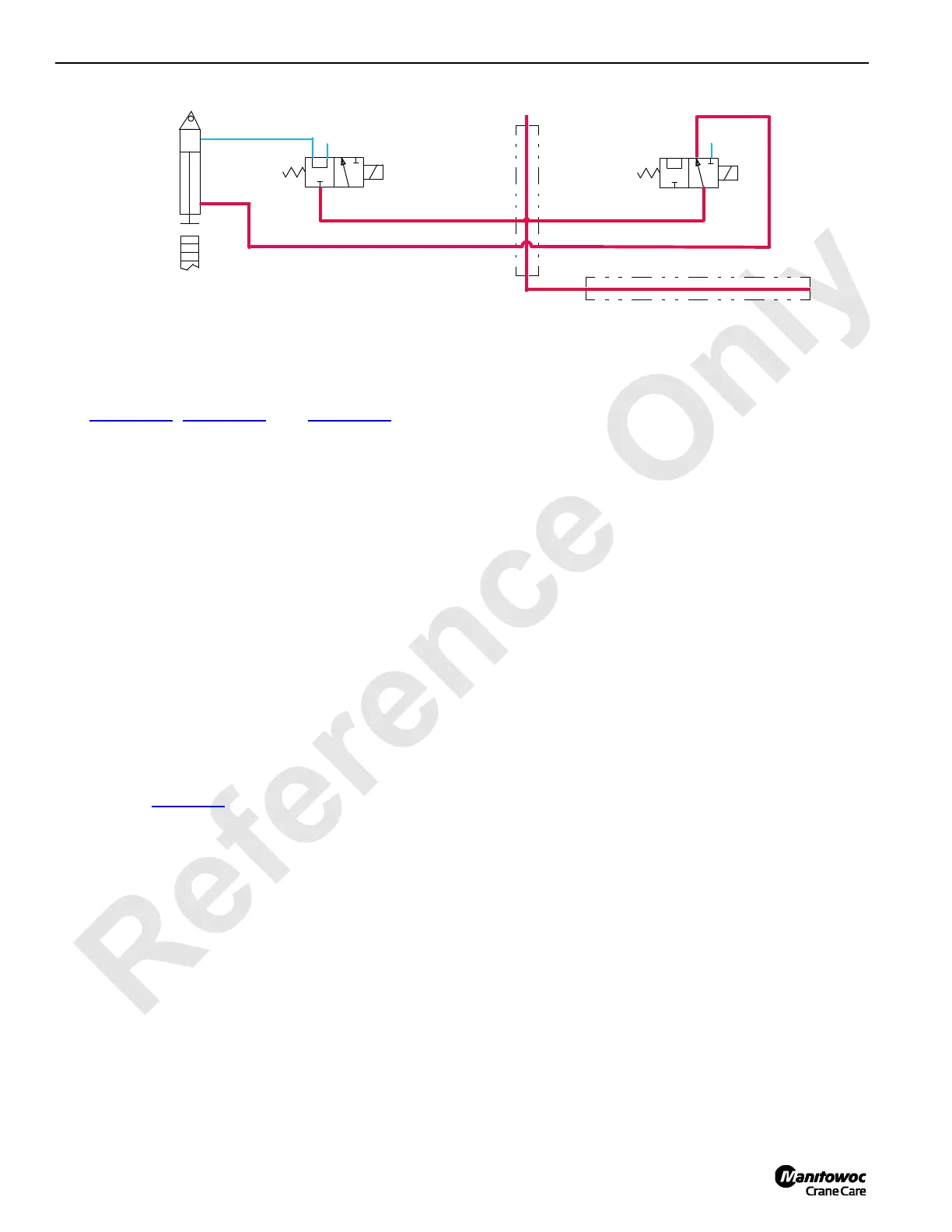
MAIN AIR MANIFOLD
BOOM HOIST
BOOM HOIST
PAWL IN
AS-13
AS-14
PAWL CYLINDER
P
P
E
A
E
A
BOOM HOIST
PAWL OUT
BOOM HOIST
DRUM FLANGE
AS-16 (LUFFING JIB)
AS-15 (LUFFING JIB)
(LUFFING JIB)
(LUFFING JIB)
(LUFFING JIB)
(LUFFING JIB)
FIGURE 1-27

 Loading...


