POWER TRAIN 2250 SERVICE/MAINTENANCE MANUAL
7-12
Published 11-06-15, Control # 040-13
ENGINE COOLING SYSTEM — PAST
PRODUCTION
General
The cooling system consists of a horizontal radiator
(mounted above engine), a hydraulically driven blower-type
fan, and an auxiliary tank.
Cooling System Operation
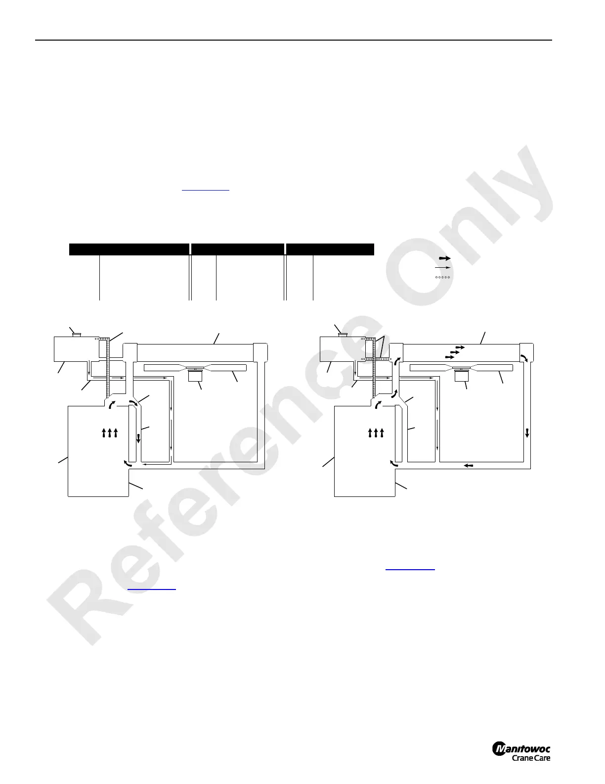
Cooling system flow is illustrated in Figure 7-11.
The cooling system is of the deaeration type, which
continually removes air from the system, as follows:
1. A small percentage of total coolant flow is circulated
through vent lines to auxiliary tank.
2. Since coolant circulation is very slow in auxiliary tank, air
separates from coolant.
3. Air collects at top of auxiliary tank. When pressure rises
to 7 psi (0,5 bar), relief in fill cap opens to exhaust air
through overflow line.
4. Deaerated coolant returns to system through make-up
line.
Auxiliary Tank Mounting
The auxiliary tank is fastened to the rear of the radiator with
spring-loaded linkage which provides two positions:
Operating Position (Figure 7-12
) places the auxiliary tank
at a level higher than the radiator. The tank must be in this
position to ensure proper deaeration of the cooling system.
The tank is raised to the operating position by spring force
when the gantry is raised.
Storage Position (Figure 7-12
) which places the auxiliary
tank below the maximum shipping height.
The tank is lowered to the storage position by the arm on the
gantry when the gantry is lowered.
FIGURE 7-11
Closed Thermostat
A678
Open Thermostat
MAIN FLOW
MAKE-UP FLOW
DEAERATION FLOW
Item Description Item Description Item Description
1
Engine
5
Make-Up Line
9
Radiator
2
Water Pump Housing
6
Vent Lines
10
Fan
3
Thermostat Housing
7
Auxiliary
11
Motor
4
Bypass Line
8
Fill Cap
1
2
3
4
5
6
7
8
9
10
11
1
2
3
4
6
7
8
11
5
10
9

 Loading...


