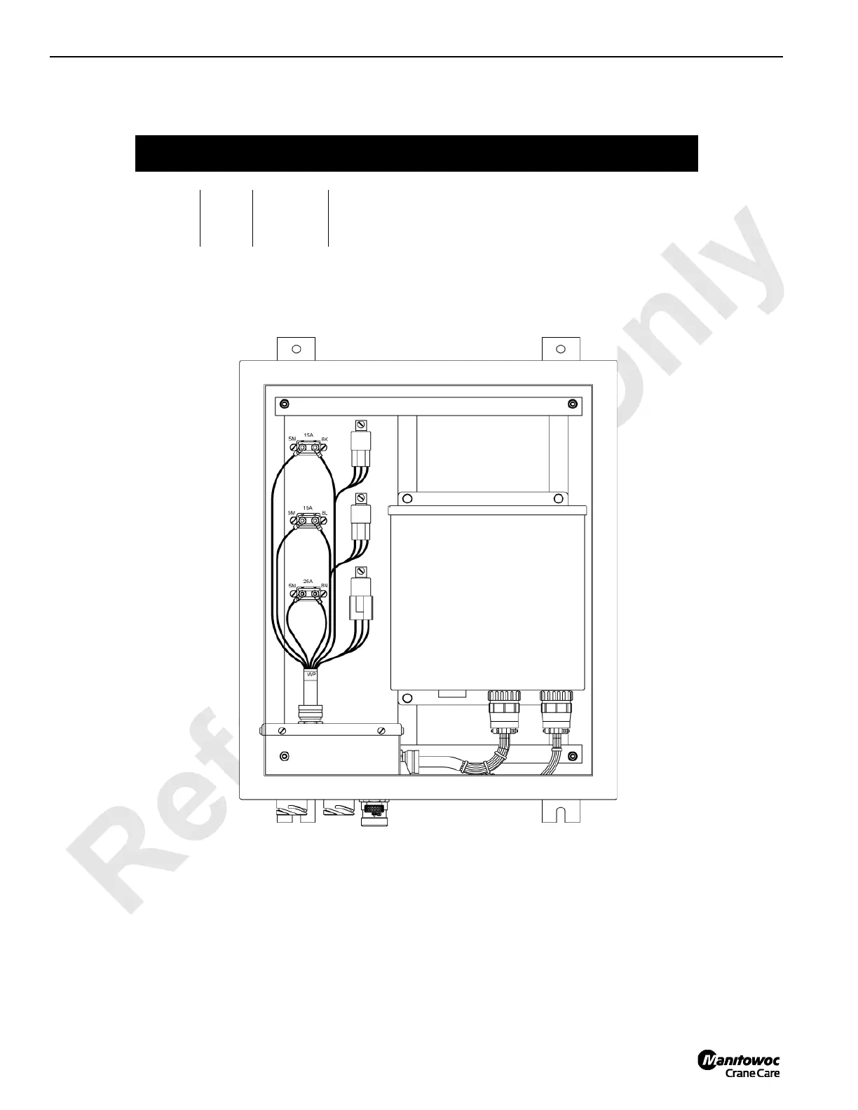
Home
Manitowoc
Construction Equipment
2250
Manitowoc 2250 Service And Maintenance Manual
4
of 1
of 1 rating
410 pages
Give review
Manual
Specs
To Next Page
To Next Page
To Previous Page
To Previous Page
Loading...
Reference
Only
ELECTRIC SYSTEM
2250 SERVICE/MAINTENANCE MANUAL
3-8
Published 1
1-06-15,
Control # 040-13
Circuit
Breaker
Amp
s
Wir
e No
.
Description of Items Protected
MAX-ER 2000 Enclosure Junction Box
1
15
8K
Main Junction Box
2
15
8L
Drum 9 Pawl Relays
3
25
8N
MAX-ER Programmable Controller
A
1
9
1
0
3
FIGURE
3-7
MAX-ER 2000 Junction Box
Enclosure
1
2
3
Main Junction Box
MAX-ER
Programmable Controller
183
185
Table of Contents
Table of Contents
5
Section 1
17
Continuous Innovation
17
Safety Messages
17
General
17
Safety Alert Symbol
17
Signal Words
17
Safe Maintenance Practices
17
Maintenance Instructions
18
Safe Maintenance Practices
18
Environmental Protection
19
Identification and Location of Components
20
Past Production and Tier 3 Engine Components
36
Tier 4 Engine Components
38
Crane Description of Operation
40
General Operation
40
Hydraulic Components
41
Hydraulic Tank
41
Shutoff Valve
41
Suction Manifold
41
Return Manifolds
41
Hydraulic Pumps
41
Charge Pressure
42
Hydraulic Motors
42
Main Pressure Monitoring
43
Basic Operation
43
Accessory Systems
45
Pressurized Air Supply
47
Engine Controls
48
Drum Identification
48
EPIC® Programmable Controller (PC)
49
Digital Display
49
Rated Capacity Indicator/Limiter (RCL)
49
Crane Modes
49
Electrical Power to Operator's Cab
50
Pressure Senders and Speed Sensors
52
Limit Switches and Faults
52
Hydraulic Brake Systems
52
Load Drum Air Brakes
53
Working (Service) Brakes
54
Load Drum Clutch Release System
54
Drum Pawls
55
Swing System Operation
56
General
56
Swing Brake and Swing Holding Brake
56
Swing Lock (Past Production)
56
Swing Right or Left
56
Travel System Operation
58
General
58
Travel Brakes
58
Two-Speed Travel Operation
58
Travel Detent Selector
58
Travel Forward and Reverse
58
Boom Hoist/Luffing Jib System Operation
61
General
61
Brake and Pawl
61
Boom Hoist/Luffing Jib Raise
61
Boom Hoist/Luffing Jib Lower
62
Load Drum System - Full Power
64
General
64
Drum Brake
64
Load Drum Hoisting
64
Load Drum Lowering
66
Dual Load Drum Motor Operation
66
Load Drum System - Free Fall
69
General
69
Load Drum Hoisting - Free Fall
69
Load Drum Lowering - Free Fall
69
Upper Accessory System Components
72
General
72
Jacking Cylinders
72
Adapter Frame Pin Cylinders
76
Gantry Cylinders
78
Lower Accessory System Components
80
General
80
Boom Hinge Pins
80
Boom Butt Handling Cylinder
82
Rigging Winch
84
Crawler Frame Pins
85
Air System Components
87
Counterweight/Back Hitch Pins
87
Hydraulic Quick Disconnect
88
General
88
MAX-ER™ 2000 Description of Operation
91
MAX-ER Components
91
MAX-ER Hydraulic Attachments
91
Auxiliary Pump
91
MAX-ER Accessory Valve
92
MAX-ER Pressurized Air Supply
92
EPIC® Programmable Controller
94
MAX-ER Modes
95
Electrical System
95
MAX-ER Remote Switch Assembly
95
Mast Back Hitch Pins Remote Switch
95
Digital Display
95
Pressure Senders and Speed Senders
95
Limit Switches
96
Back Hitch Pins
97
Back Hitch Pins Extend/Retract
97
Tongue Cylinder
98
Tongue Cylinder Extend
98
Tongue Cylinder Retract
99
Counterweight Jack Cylinders
100
Jack Cylinder(S) Extend
100
Jack Cylinder(S) Retract
101
Steering Pin Cylinders
103
Steering Pin Cylinders Disengage
103
Steering Pin Cylinders Engage
103
Steering Arm Cylinders
105
Steering Cylinders Extend (Swing/Crab)
105
Steering Cylinders Retract (Straight)
106
Counterweight Strap Cylinders
108
Counterweight Switch
110
Counterweight Strap Cylinders Lower
110
Counterweight Strap Cylinders Raise
110
Mast Stop Raising and Boom Stop
111
Mast Stop Raising Cylinders
111
Boom Stop Cushion Cylinders
111
Mast Stop
112
Mast Stop Cylinders
112
Mast Stop System Operation
112
Jib Stop Cylinders
113
Jib Stop System Operation
113
Drum 9 Operation
114
Drum 9 Brake
115
Drum 9 Hoisting (MAX-ER Mode)
115
Drum 9 Lowering (MAX-ER Mode)
117
Hydraulic Cooler Fan Drive - Tier 4 Only
119
Description
119
Maintenance
119
Hydraulic Schematics
125
Hydraulic System - General
125
Checking and Replacing Hydraulic Hoses
125
Hydraulic System Maintenance
126
Safety
126
Storing and Handling Oil
126
Storing and Handling Parts
126
Inspecting System
126
Servicing Pumps
127
Cleaning Fill Cap Assembly
127
Replacing Suction Filter Element
128
Changing Oil
129
Tightening Hydraulic Connections
131
General
131
Pipe Thread Connection
131
SAE Straight Thread Connection
131
ORS Connection
132
Split Flange Connection
132
SAE Flare Connection
133
Programmable Controller Calibration Procedures - Past
134
General
134
Controls Calibration
134
Pressure Sender Calibration
134
Programmable Controller Calibration Procedures - Current
134
Pressure Sender Calibration
135
Controls Calibration
135
Pressure Sender Replacement
136
General
136
Disc Brake Operational Test
138
General
138
Operational Test
138
Shop Procedure
140
General
140
Pump Identification
140
Pump Port Identification
140
Pump Components
140
Initial Oil Fill
141
Pressure Sender Calibration
141
Initial Start-Up
142
Controls Calibration
143
Fan and Pilot Pressure Adjustment
143
Charge Pressure Checks
143
Operating Pressure Checks
144
Boom Hoist down
144
Boom Hoist up
144
Swing
144
Auxiliary System Pressure Checks
145
Travel
145
Load Drums
145
Auxiliary System Relief Valve
145
Rotating Bed Jacking Cylinders
146
Connecting Pin Cylinders (Crawler, Boom Hinge, and Adapter Frame)
147
Boom Butt Handling Cylinder
147
Gantry Cylinders
147
System Speed Checks
148
Travel Straightness
148
Unloader Pilot Valve Maintenance
149
General
149
Adjustment
149
Maintenance
149
Moisture Ejector Valve Maintenance
150
General
150
Control Handle Positions
150
Operational Checks
150
Maintenance
150
Automatic Operation
150
Shut-Off
150
Air System Filter Maintenance
151
General
151
Daily Maintenance
151
Monthly Maintenance
151
Automatic Drain Valve Operation
152
Air System De-Icer Maintenance
152
Operation
152
Adjusting
152
Maintenance
153
Filling
153
Air Dryer Maintenance (Current Production)
155
Description
155
Operation and Leak Test
155
Disassembly
155
Cleaning and Inspection
156
Assembly
156
Preventive Maintenance
157
Every 500 Operating Hours or Every Three Months
157
Air Dryer Maintenance (Past Production)
158
Description
158
Operation
158
Every 6,000 Hours or 36 Months
158
Compressor Cut-In
158
Compressor Cut-Out
158
Maintenance
159
Breather Vent Maintenance
161
Solenoid Valve Maintenance
162
Operation
162
Air Line Connection
162
Electrical Connection
162
Maintenance
162
Normally Closed
162
Troubleshooting
162
Disassembly
162
Reassembly
162
Quick Release Valve Maintenance
164
General
164
Adjustment
164
Maintenance
166
Air Pressure Safety Switches Maintenance
166
General
166
Operation
166
Adjustment Requirements
166
Adjustment
167
Shuttle Valve Maintenance
168
General
168
Operation
168
Maintenance
168
Type a Air Regulator Maintenance
169
Installation
169
Adjustment
169
Maintenance
169
Maintenance
170
Pressure Reducing Valve Maintenance
170
Operation
170
Adjustments
170
Type S Relay Valve Maintenance
172
General
172
Operation
172
Increasing Pressure
172
Balanced Position
172
Maintenance
173
Decreasing Pressure
173
Electrical Drawings and Schematics
177
Checking or Replacing Electrical Components
177
Circuit Breaker and Fuse ID
178
General
178
Test Voltages for Crane Controller
187
General
187
Controller Board Layout
187
Abbreviations
187
Crane Controller Pin Identification
188
Crane Controller Wire Identification
194
Crane Controller Description Identification
199
Master Node Pin Identification
204
Aux Power Plant Controller Pin Identification
206
Model 2250 MAX-ER 2000™ Test Voltages
207
General
207
Controller Board Layout
207
Abbreviations
207
MAX-ER Controller Pin Identification
208
MAX-ER Controller Wire Identification
210
MAX-ER Controller Description ID
212
Digital Display Readings
214
General
214
Operating Conditions
214
Operating Limits
214
System Faults
214
Selecting Display Language
215
Drum Identification
222
Diagnostic Display
223
General
223
Drums 1, 2, and 3 (Crane Load Drums)
223
Drum 4 (Boom Hoist)
223
Drum 5 (Luffing or Auxiliary Hoist)
223
Drum 9 (MAX-ER 2000 Load Drum)
223
Swing (Crane)
224
Track (Crane Crawlers)
224
Mast Accumulator
224
Mxr (Max-Er 2000)
224
A1 (Handles)
225
A2 (Programmer's Screen)
225
D1 and D2 (Digital Outputs and Inputs)
226
EPROM Replacement
230
Dielectric Grease
232
Section 4
233
Automatic Boom Stop Adjustment
235
General
235
Operation
235
Maintenance
235
Operating Angle
235
Setup Angle
235
Limit Bypass Test
236
Adjustment
238
Maximum (MAX) Boom Stop
238
Minimum (MIN) Boom Stop
238
Setup Boom Angle
239
Physical Boom Stop
239
General
239
Operation
239
Maintenance
241
Lowering Boom Stop to Shipping Position
241
Raising Boom Stop to Working Position
241
Adjustments
241
Boom Stop Rod Ends
241
Angle Indicator Adjustment
241
General
241
Boom Stop Engagement
241
Boom Stop Compression
241
Disconnecting Luffing Jib Angle Indicator
243
Sending Unit Assembly
243
Pendulum-Type Potentiometer
243
Adjusting Angle Indicator
244
Solid State Sensor
244
Boom Hoist Ratchet and Pawl Adjustment
246
General
246
Limit Switch Adjustment
246
Return Spring
246
Strap Inspection and Maintenance
248
Inspection
248
Identifying Straps
248
Frequent Inspection
248
Periodic Inspection
248
Cranes Not in Regular Use
248
Replacement Specifications
249
Corrosion or Abrasion
249
Straightness
250
Flatness
250
Elongated Hole
251
Length
251
Storing Straps
252
Removing Straps from Service
252
Inspection Checklist
252
Lattice Section Inspection and Lacing Replacement
252
Minimum Bail Limit Adjustment
259
General
259
Weekly Maintenance
259
Wire Rope Removal
261
Electric Wiring
261
Minimum Bail Limit Adjustment
261
Block-Up Limit Control Adjustment
262
General
262
Block-Up Limit Control Operation
263
Load Block Level Transmitter
263
Installation
263
Storing Electric Cord
263
Disconnecting Block-Up Limit Control
264
Removing Jib or Boom Point
264
Maintenance
264
Adjustment
266
Drum Brake Inspection and Adjustment
267
Description
267
Brake Inspection and Adjustment
269
Treadle Valve Checks
270
Treadle Valve Adjustments
270
Brake Actuator Overhaul
271
Removal
271
Repair
271
Rework - Current Production Actuators
271
Brake Release Adjustment
272
Rework - Past Production Actuators
272
Installation
272
Drum Clutch Inspection and Adjustment - Standard
274
Description
274
Inspection and Adjustment
274
Band Disassembly and Assembly Notes
276
Clutch Cylinder Overhaul
277
Cylinder Removal
277
Cylinder Disassembly
277
Cylinder Assembly
277
Cylinder Installation
277
Drum Clutch Inspection and Adjustment - Right Rear Drum Clutch (421339)
279
General
279
Inspection and Adjustment
280
Band Disassembly and Assembly Notes
281
Cylinder Rod Marking
281
Gearbox Cooling Blower
281
Slack Line Sensor Adjustment
282
General
282
Light Sensor Adjustment
282
Slack Line Indicator Calibration
282
Drum Pawl Adjustment
283
General
283
Limit Switch Adjustment
283
Return Spring
283
Wire Rope Lubrication
284
Wire Rope Inspection and Replacement
284
General
284
Keeping Records
284
Inspecting Wire Rope
284
Frequent Inspection
284
Inspecting Rope Not in Regular Use
285
Replacing Wire Rope
285
Periodic Inspection
285
Wire Rope Diameter
285
Broken Wires
285
Wear and Other Damage
286
Distributing Wire Rope Wear
287
Sheave, Roller, and Drum Inspection
288
Load Block and Hook-And-Weight Ball Inspection
291
Manual Release of Swing Brake and Lock
297
Manual Release Procedure
297
Section 7
297
Battery Maintenance
301
Safety Information
301
Causes of Battery Failure
301
Multiple Battery System
301
Overcharging
301
Undercharging
301
Lack of Water
301
Hold-Downs
301
Overloads
301
Maintenance
302
Weekly - Check Electrolyte Level
302
Every 2 Months - Test Batteries
302
Charging
303
Storage
303
Battery Disconnect Switch
303
Quarterly
303
Engine Diagnostics (Celect Plus Engine)
304
General
304
Controls
304
Engine Running Diagnostics
304
Engine off Diagnostics
304
Engine Stop Light
304
Engine Warning Light
304
Engine Maintain Light
304
Engine Diagnostics (QSX 15 Engine)
306
General
306
Diagnostic Lights
306
Engine off Diagnostics
306
Engine Stop Light
306
Engine Warning Light
306
High Exhaust System Temperature - Tier 4 Only
306
DPF on - Tier 4 Only
306
DPF Regeneration Inhibit - Tier 4 Only
306
Engine Air Cleaner Maintenance - Tier 3 Engine
308
Inspection
308
Service
308
Daily
308
Engine Air Cleaner Maintenance - Tier 4 Engine
309
Inspection
309
Daily
309
Weekly
309
Service
310
Air Cleaner - Tier 4 Only
311
Engine Cooling System - Past Production
312
General
312
Cooling System Operation
312
Auxiliary Tank Mounting
312
Maintenance
313
Daily Maintenance (Start of each Shift)
313
Semiannual Checks
313
Engine Cooling System with Cummins QSX-15 Engine - Current Tier 3
314
General
314
Cooling System Operation
314
Maintenance
315
Daily Maintenance (Start of each Shift)
315
Draining Radiator
316
Filling Radiator
316
Semiannual Checks
316
Engine Cooling System Fill - Current Production Tier 4
317
General
317
Cooling System Operation
317
Maintenance
317
Draining Radiator
317
Daily Maintenance (Start of each Shift)
317
Semiannual Checks
317
Filling Radiator
318
Engine Throttle Adjustment
318
Cummins N14 - C450 Engine
318
General
318
Foot Throttle Linkage Adjustment
319
Electronic Fuel Control Adjustment
319
Cummins N14 - C525 Engine
321
General
321
Foot Throttle Linkage Adjustment
321
Engine Speed Calibration
321
Cummins N14 - C525E Engine
322
Cummins QSC8.3, QSM11, or QSX15 Engine
322
General
322
Foot Throttle Linkage Adjustment
322
Engine Speed Calibration
322
Caterpillar 3406C Engine
323
General
323
Foot Throttle Linkage Adjustment
323
Electronic Fuel Control Adjustment
323
Test Voltages
324
Diesel Particulate Filter Regeneration - Tier 4 ONLY
325
General
325
Regeneration
325
Passive Regeneration
325
Active Regeneration
325
Stationary Regeneration
325
Pump Drive Disconnect
326
General
326
Adjustment
326
Turntable Bearing Bolt Torque
331
Bearing Installation
331
Torque Requirements
331
Bolt Replacement
331
Lubrication
331
Torque Values
331
Torque Sequence
331
Torque Intervals
331
Crawler Adjustment
332
Maintenance
332
Tread Slack Adjustment
333
Adjustment Guideline
333
Adjustment Procedure
333
Hydraulic Hand Pump
334
Assembly
334
Maintenance
334
Air Removal
334
Pump Operation
334
Rotating Bed Level Sensor
336
To Reset (Re-Zero) the Level Sensor
336
To Re-Calibrate the Rotating Bed Level Sensor
336
Lubrication Guide
339
Lube and Coolant Product Guide
339
Section 10
339
Basic Troubleshooting
343
Safety Summary
343
General Guidelines
344
Test Equipment
344
Troubleshooting Charts
345
Testing Components
377
Test 1 - Battery Test (12 and 24 Volts DC)
377
Test 2 - Checking Resistance at Engine Temperature Switch
378
Test 3 - Checking Resistance at Engine Oil Pressure Switch
379
Test 4 - Electric Fuel Control (EFC) Box Test Points
380
Test 5 - Testing the Pump EDC and Motor PCP
381
Test 6 - Cleaning and Adjusting the Engine RPM Transducer
382
Test 7 - Location of Motor Ports
383
Test 8 - Testing for Pump and Motor Leakage
384
Test 9 - Location of Pump Ports
385
Test 10 - Checking Voltage at the Hydraulic Brake Valve
386
Test 11 - Manually Stroking the Pump
387
Test 12 - Testing for Voltage at the Fuse Box
388
Test 13 - Checking Voltage at the Control Handle
389
Test 14 - Adjusting the Control Handle Potentiometer
390
Test 15 - Checking System Voltage at the Air Solenoid Panel
391
Test 16 - Checking System Voltage at the Hydraulic Valve Assemblies
392
Test 17 - Checking Pump Charge Pressure and Electrical Test
394
Previous Production
394
Current Production -SN 2251179, 2251183, 225185 & up
394
Test 19 - Adjusting Pump Charge Pressure Relief
394
Test 18 - Setting the Pump Pressure
395
Test 19 - Adjusting Pump Charge Pressure Relief
396
Test 20 - Setting Pump Neutral
397
Test 21 - Checking Voltage at the Speed Encoders
398
Test 22 - Adjusting the Counterbalance Valves
399
Test 23 - Servicing the Motor Loop Flushing (Purge) Valves
400
Test 24 - Checking Hydraulic Brake Pressure
401
Test 25 - Checking and Adjusting Auxiliary System Working Pressure
402
Test 26 - Checking Pin Cylinder Seals
404
Test 27 - Actuating the Solenoid Valve Manual Overrides
405
Other manuals for Manitowoc 2250
Operator's Manual
312 pages
Service Maintenance Manual
370 pages
4
Based on 1 rating
Ask a question
Give review
Questions and Answers:
Need help?
Do you have a question about the Manitowoc 2250 and is the answer not in the manual?
Ask a question
Manitowoc 2250 Specifications
General
Brand
Manitowoc
Model
2250
Category
Construction Equipment
Language
English
Related product manuals
Manitowoc Grove YB5515-2
152 pages
Manitowoc 14000 2 Series
4 pages
Manitowoc 16000 Series 2
2 pages
Manitowoc Grove RT765E-2
178 pages
Manitowoc Grove RT530E-2
168 pages
Manitowoc Shuttlelift CD5515-2
152 pages
Manitowoc National Crane 600E-2
122 pages
Manitowoc Grove TMS9000-2 Series
430 pages
National Crane NBT30H-2
132 pages
Manitowoc 14000
270 pages
Manitowoc GROVE GMK5150L
1040 pages
Manitowoc Grove GMK6300L
1004 pages