INTRODUCTION 2250 SERVICE/MAINTENANCE MANUAL
1-28
Published 11-06-15, Control # 040-13
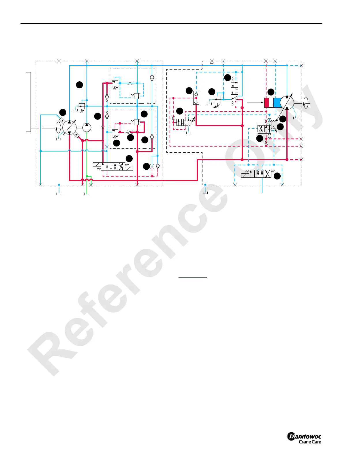
The pressure limiting relief valve (1) serves as pilot valve to
open system relief valve (5) when desired relief pressure
setting is reached. For example, if a pressure imbalance
occurs on both sides of flow restrictor (9), pressure limiting
valve opens and system relief valve relieves system
pressure.
Hydraulic fluid is directed to tank through relief valve (7) or
the flow is transferred to low-pressure side of system through
the make-up check valve (8).
Each variable displacement motor, except travel, begins
operation at maximum displacement (high torque, low
speed) and shifts to minimum displacement (low torque, high
speed) if torque requirement is low. The motor remains in
maximum displacement until servo PC valve (10) receives a
command from PCP valve (11) to direct system pressure and
flow from shuttle valve (12) to minimum displacement side of
servo cylinder (13) that shifts motor.
As PCP valve opens in proportion to output voltage received
from the PC, pilot line pressure is directed to shift servo PC
valve. After overcoming adjustable valve spring (14) and
valve spring (15), servo PC valve shifts and directs fluid to
stroke motor at minimum displacement output. If the load at
the motor shaft increases, force on adjustable valve spring
increases. This shifts servo PC valve to de-stroke the motor
to maximum displacement for safe load handling.
Optional drum 1 motor, boom hoist motor, and the single
motor drive for split rear drum, also have a PCOR (Pressure
Compensating Over-Ride) valve (16) that is enabled when
system pressure of 4,930 psi (340 bar) is reached. When
system pressure exceeds the PCOR setting, the valve shifts
to direct flow from shuttle valve into maximum displacement
side of servo cylinder.
The PCOR valve over-rides the command from servo PC
valve, increasing motor displacement and output torque and
reducing output speed. When PCOR valve closes, control of
the motor returns to servo PC valve.
The Optional dual motor drive for split rear drum shaft
(Figure 1-29
) has one bi-directional, variable displacement
motor with 12 volt proportional solenoid control along with
one fixed displacement motor mounted in tandem.
Proportional motor displacement is set to override to
maximum (high torque) at 4,500 psi (310 bar) preventing
high pressure motor failure.
The travel motor servo is opposite of other system motors.
The travel variable displacement motors begin operation at
minimum displacement (low torque, high speed). The motor
shifts to maximum displacement (high torque, low speed)
when starting torque is required and back to minimum
displacement when in motion if load is below a preset
pressure of 3,770 psi (260 bar). Depending on motor system,
servo uses internally or externally supplied pressure to
perform the shifting operation. Servo control fluid is supplied
from high-pressure line of motor port A or B and shifts shuttle
valve and servo control valve before entering servo cylinder.
Continuous changing of closed-loop fluid occurs through
leakage in pumps, motors, and loop flushing valves.
RF-03
FIGURE 1-12
(23 bar)
340 PSI
T2
T3
A
MAX.
P
U
M
P
D
R
I
V
E
B
B
A
A
DC
EGFD
OUTPUT
INPUT
PUMP
MOTOR
B
A
M8
M7
M3M4M6L2
M9
M2
M5
M1
11
4
6
18
13
5
10
9
15
14
7
16
12
17
2
1
8
3
DISP.
T1
 Loading...


