Procedures for Testing with the DX Host
98 Baker DX 71-030 User Guide EN V10 www.megger.com
Surge Testing Procedure for Single-Coil Mode
The preceding Surge test section described three-phase coil testing. This section focuses on
single-coil testing.
A common application is quality control, during which a group of identical coils is tested. The
process starts with a known good coil (reference) from which to make comparisons.
NOTE: Refer to “Determining a Known-good Coil to Use as a Reference” found on the preceding pages for
information about identifying known good coils and using the reference features.
CAUTION: THIS PROCEDURE USES THE HIGH-VOLTAGE TEST LEADS. EXERCISE CAUTION TO
AVOID INJURY.
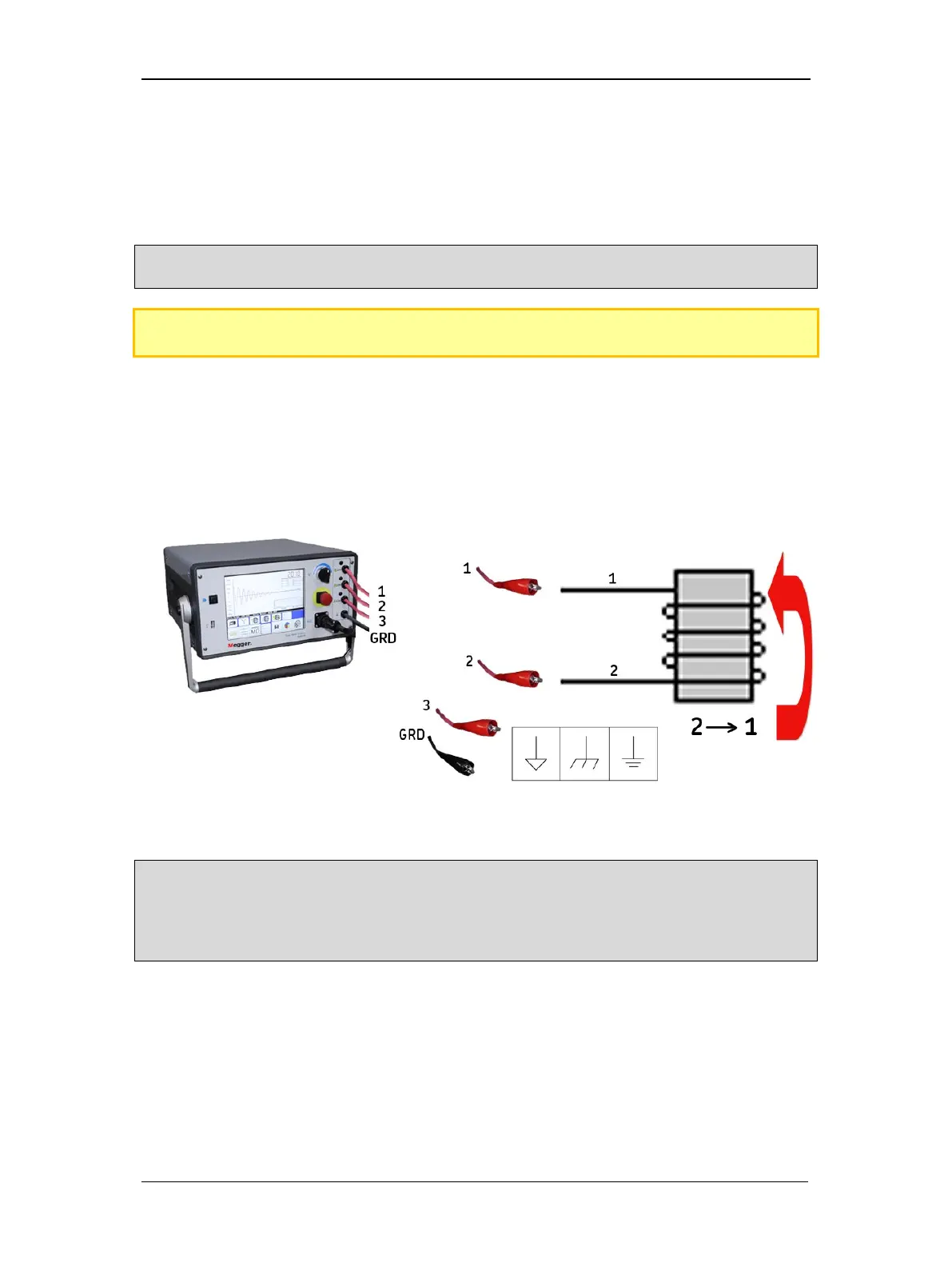
1. Connect red tester lead 1 to coil lead 1 and red tester lead 2 to coil lead 2.
2. When the select active lead icon on the Baker DX is 12, red tester lead 1 is active
(hot) and red tester lead 2 is the return path (ground potential).
3. Red tester lead 3 and the black ground lead are also at ground potential. They can be
connected to a field pole, iron core, or frame if applicable—but it is not required.
Figure 108. Testing single coils with the Baker DX—three-lead testers.
NOTE: For Baker DX testers using the single-lead option, connect the red test lead to coil lead 1 and the black
ground lead to coil lead 2.
When using the process for low-impedance coil or armature testing, other probes or test fixtures will be used
to make connections. Refer to the specific test procedures for details.