Setting up the Baker ZTX
50 Baker DX 71-030 User Guide EN V10 www.megger.com
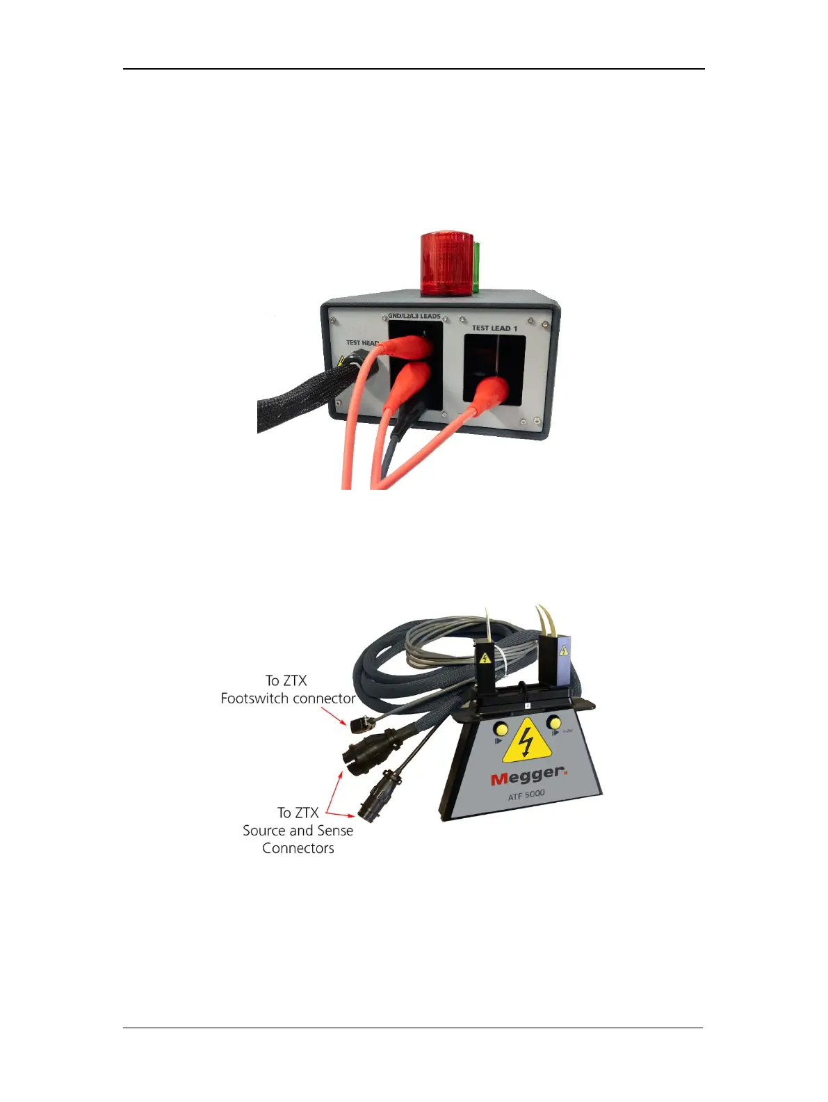
4. Connect the high-voltage test leads of the Baker DX to the Baker ZTX unit’s recessed
bars on the rear of the unit as labeled:
Test lead 1 to the bar labeled “Test Lead 1.”
Test leads 2 and 3, and the Ground lead to the bar labeled “GND/L2/L3 Leads.”
Figure 51. DX leads and fixture connections to Baker ZTX rear panel.
5. Connect the bar-to-bar test fixture to the black braided test head cable. There are two
connectors: a small circular one (sense) and a large one (source). Be sure both
connections are properly made.
Figure 52. ATF-5000 armature test fixture.
6. After completing the setup process, ensure that the Baker DX is plugged into a good
grounded source (the Baker ZTX is powered by the DX).