Procedures for Testing with the DX Host
megger.com 63
Resistance Test Procedures
1. Connect low-voltage resistance test leads as described in chapter 9 “Setting up fixtures,
test accessories, and lead connections.”
CAUTION: DISCONNECT AND LAY ASIDE THE HIGH-VOLTAGE TEST LEADS WHEN PERFORMING
RLC TESTS.
2. Select the folder and record to use and check the Status Bar to ensure that the Active
Folder and Active Record display the desired folder and record to be used for the
subsequent RLC tests.
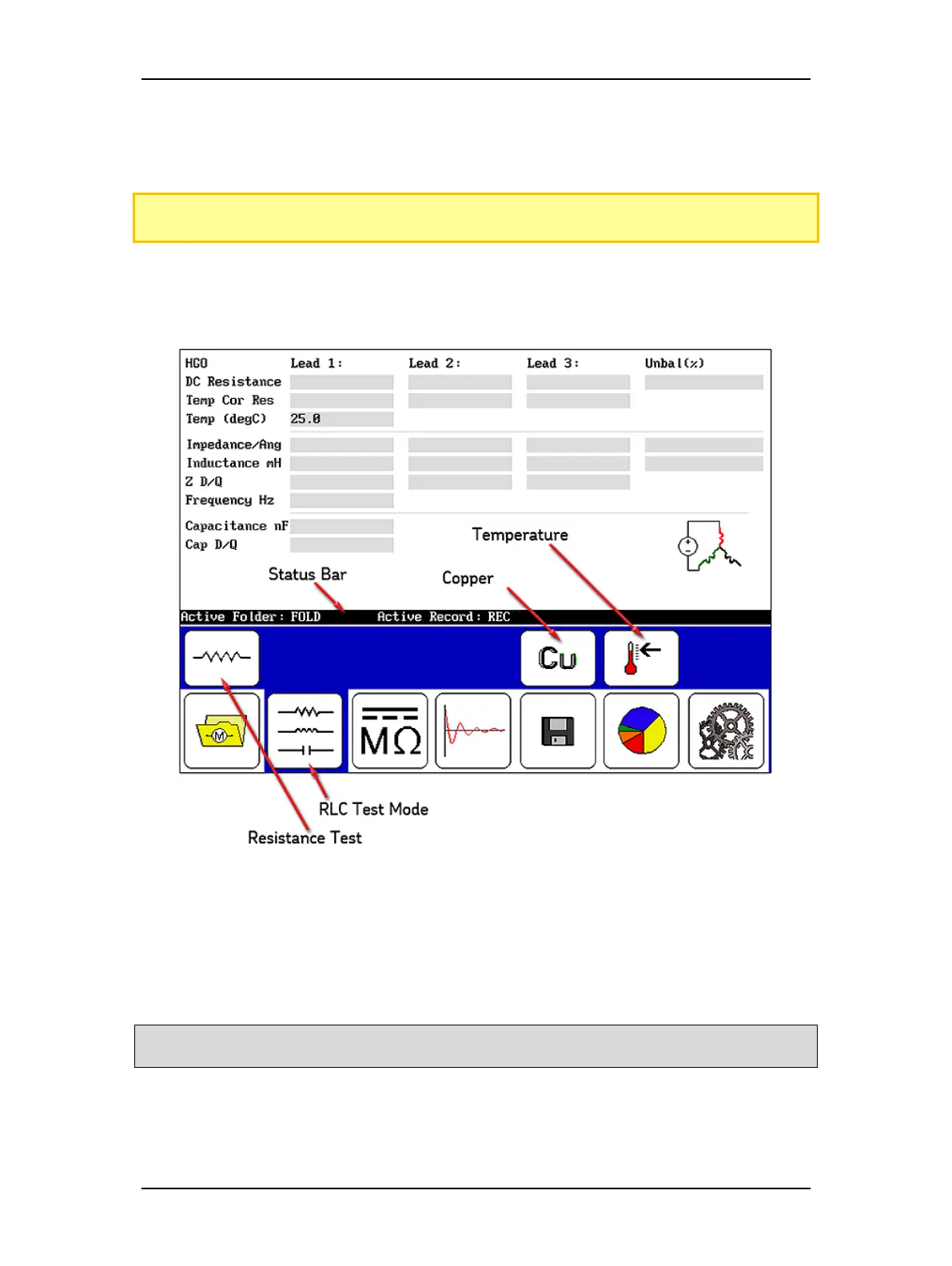
Figure 66. Resistance test start screen.
3. Touch the RLC Test Mode icon.
4. Ensure that the Resistance Test Selection icon is set to resistance test.
5. If performing temperature compensation, touch the icon for the proper type of
conductor metal: aluminum or copper (Copper icon shown above).
NOTE: In the test start screen as shown above, the value that first appears in the Temp (degC) field is
originally defined in the system settings. If needed, you can change this value in the next step.