Procedures for Testing with the DX Host
megger.com 115
Low-voltage Armature or Coil Tests Using the DX Host
Low-voltage armature or coil mode is used to plot resistance, inductance, phase angle, and
impedance measurements taken over different coils or over different armature bars (windings).
For example, in the case of testing a DC armature, you can take test measurements on each bar
on the commutator. All measurements are made on each coil or armature bar. The results are
plotted with respect to the different coils tested.
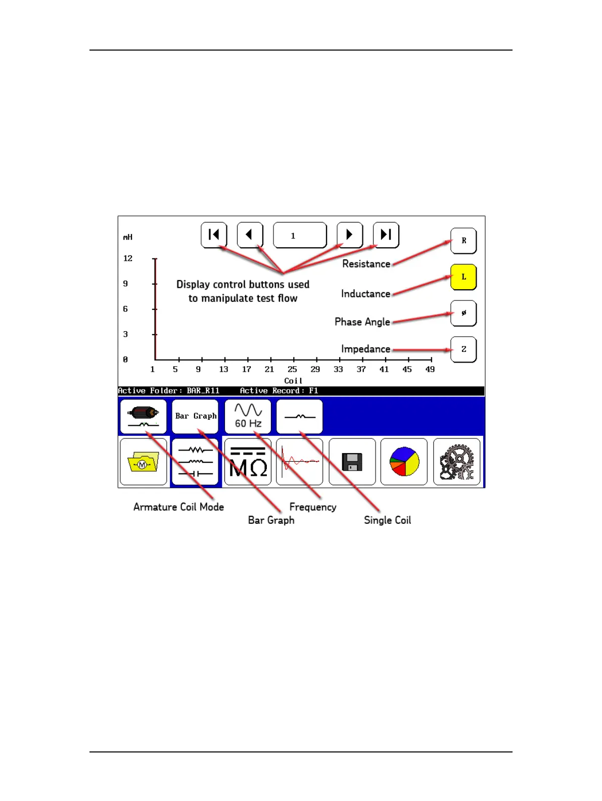
The display control buttons at the top move you through which coil or armature bar
measurement you want to see. The buttons along the right edge are used to select the type of
test measurement you want to plot.
Figure 128. Low-voltage armature or coil mode screen elements.
In the submenu, the first icon from the left—the Armature Coil Mode icon—shows you that
you are in low-voltage armature or coil mode. The Bar Graph icon identifies the display format
selected. Touching the icon allows you to change the type. The frequency displayed is shown by
the next icon, which again can be changed by touching the icon. The frequency is typically that
used to operator the device under normal conditions.
The fourth icon—Single Coil in this case—shows the type of coil being tested. That selection
can also be changed by touching the icon. This icon is a notation in the result that also appears
in the report when printed.