Procedures for Testing with the DX Host
116 Baker DX 71-030 User Guide EN V10 www.megger.com
Low-voltage Armature or Coil Test Procedures
1. Remove the low-voltage RLC test leads and set them aside.
2. Connect the low-voltage armature test probes to the RLC test leads connector. (The
standard low-voltage RLC test leads 1 and 2 can be used to test single coils.)
3. Check the Status Bar to ensure that the Active Folder and Active Record fields
display the intended target destinations for your test data.
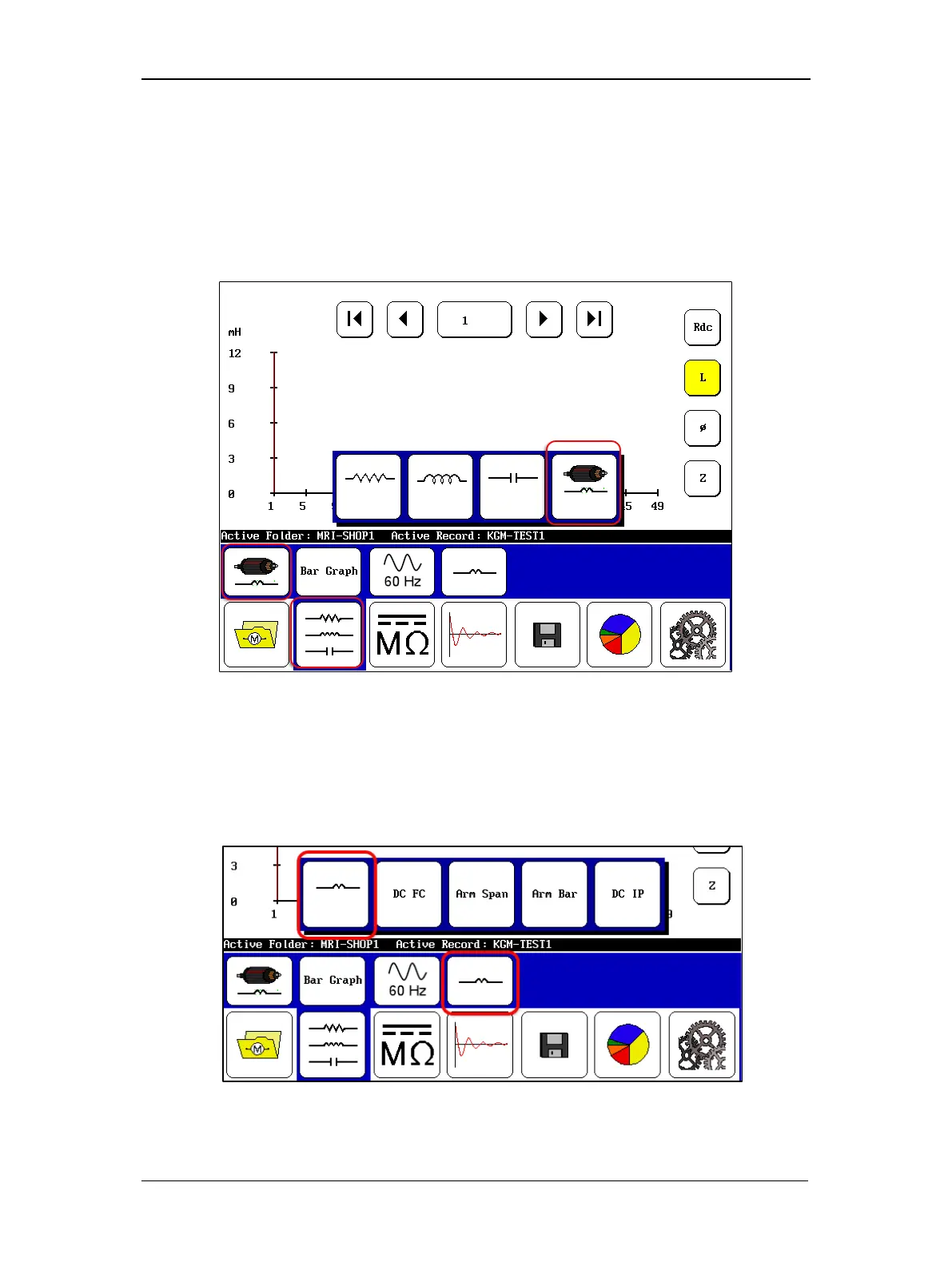
Figure 129. Low-voltage armature or coil test start screen.
4. Set up the start screen start screen as shown above by touching the RLC Tests mode
icon in the Mode Menu then selecting the Armature Coil Mode icon in the Mode
Submenu.
5. Select the coil or winding type to test as shown in the example below.
Figure 130. Selecting coil type to test—single coil selected.
 Loading...