Baker DX Instrument Overview
10 Baker DX 71-030 User Guide EN V10 www.megger.com
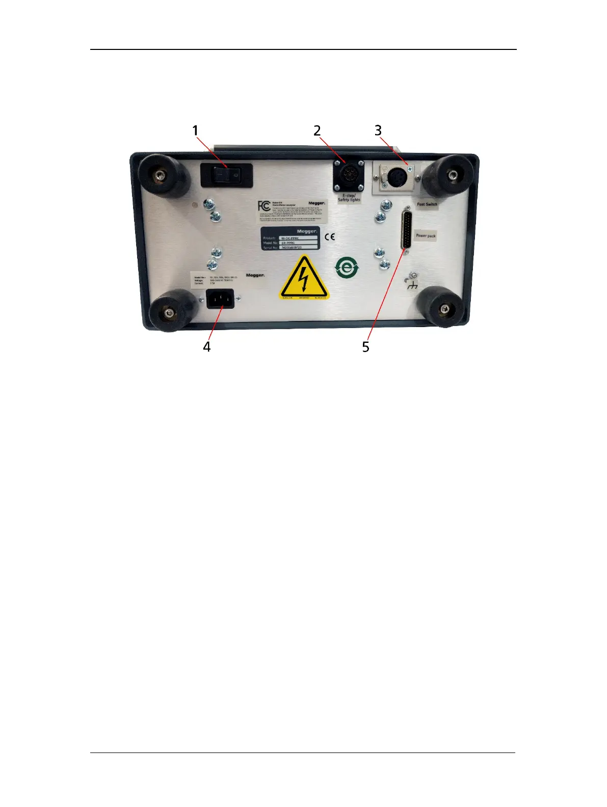
Rear Panel Connections
The graphic below identifies the connections found on the rear of the DX.
Figure 6. Rear panel connections.
1. DX on/off switch.
2. Remote E-stop and Safety Lights receptacle
3. Footswitch receptacle.
4. DX AC power receptacle.
5. Power Pack interconnect receptacle
Configuration Options
The Baker DX series includes seven models: DX4 (4 kV), DX6 (6 kV), DX6HO (6 kV), DX12 (12
kV), DX12HO (12 kV), the DX15 (15 kV), and the DX15A (15 kV with built-in ZTX). They have
common base functions, but vary by capacity.
The capacity and capability for these models can be augmented with easily-attached auxiliary
units such as power packs that extend the output capacity up to 40 kV (Baker PP30/PPX30, Baker
PP40/PPX40).
You can add low-impedance coil testing to the host with the Baker ZTX 101, or through a Baker
power pack with built-in ZTX capability (such as the Baker PP85/PPX30A).
More information is provided in the following sections.