Baker DX Instrument Overview
megger.com 9
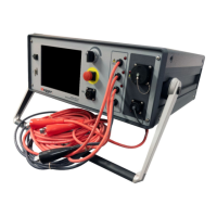
5. Voltage Output Control knob
Turn the knob clockwise to increase the applied voltage or counterclockwise to decrease the
voltage. The rate of voltage increase or decrease is set via the touch screen interface. Do not
force the knob; turning the knob harder does not cause voltage to ramp any quicker and may
damage the instrument.
6. System unit kV capacity
Each system is clearly marked on the front panel with its voltage capacity.
7. Resistance/inductance/capacitance lead port
Full Kelvin connection leads are used for resistance, inductance, and capacitance testing. Both
sides of the connection clips must be in contact with the terminal of the motor being measured.
8. Low-voltage RLC test leads
Depending on the tester model and options ordered, the tester can have three low-voltage test
leads are provided for motor test connections.
9. High-voltage test leads
Three high-voltage test leads (red) and a ground lead (black) are provided for motor test
connections The Baker DX uses high-voltage test leads for surge, Baker ZTX, and DC testing.
Keep the leads clean and dry for best measurement performance.