Baker DX User Interface Overview
20 Baker DX 71-030 User Guide EN V10 www.megger.com
Test and Function Modes
The large icons in the mode menu at the bottom of the touch screen represent the primary
test modes. The mode menu is always visible on the screen during normal operation. When
a mode menu icon is touched, the icon will be surrounded by a blue background that
indicates which mode the unit is in. The blue background also connects the selected mode
with its submenu above.
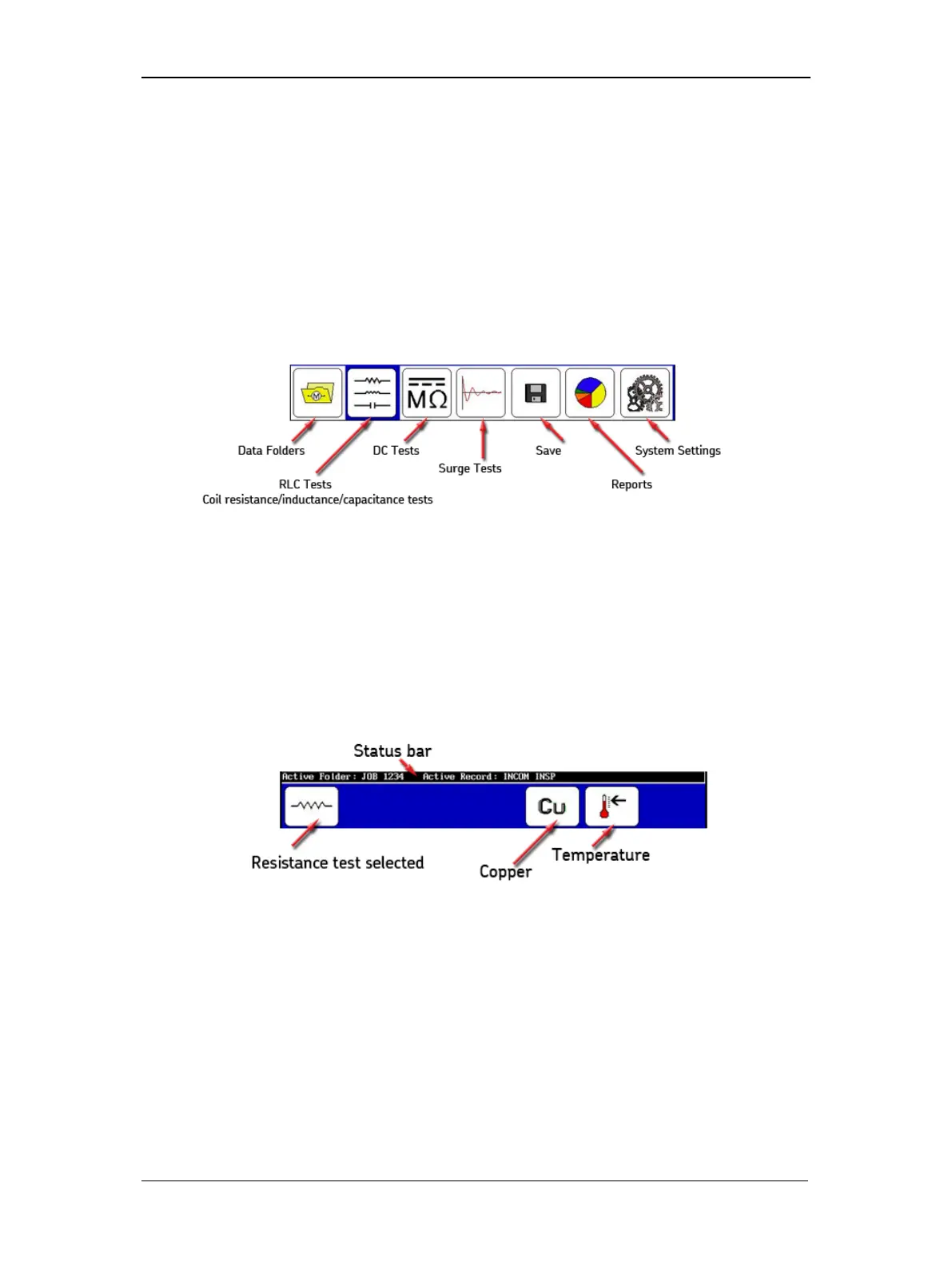
The graphic below identifies the test and function modes that become active when you
touch the corresponding icons.
Figure 18. Mode menu icon descriptions.
Mode Submenus
The control icons for each mode appear in the submenu just above the Mode Menu. The
Mode Submenu icons correspond to the Mode Menu item selected. In the following
example, we see the descriptions of the Mode Submenu icons that appear when the RLC
Tests icon is touched.
Figure 19. Mode submenu icons example.
A couple more examples of submenus follow to give you a better idea of how their content can
change depending on the test or function selected.
The single-coil testing submenu is shown in the next example. This submenu appears during a
Surge test operation when a Standalone Unit is selected along with Single-coil mode. The
third icon is used to select the active lead and the direction to start the surge flow—hot side.
The Backspace icon is used to delete tests. The Set Reference icon is used to set the selected
test as the reference. The Waveform Selection icon is used to select optional coil test displays.
The ZS Override (Zero Start Override) icon is used to tell the tester to go immediately to the