Procedures for Testing with the DX Host
megger.com 79
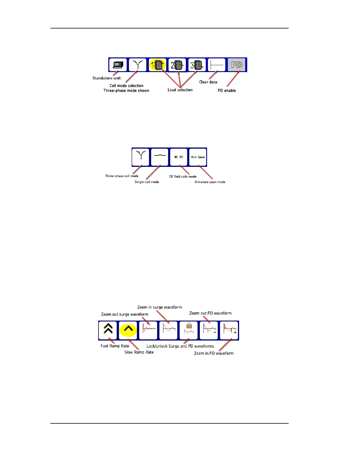
5. For the following example, touch the Standalone unit icon.
Figure 85. Surge Mode Submenu icons.
6. Touching the Coil Mode Selection icon in the Mode Submenu brings up the popup
menu shown below. You will then select from a choice of modes: three-phase mode,
single-coil mode, field coils mode, and armature span mode.
Figure 86. Coil Mode Selection popup menu.
7. For this example, touch the Three-phase coil mode icon (other options are addressed
later in this manual).
8. The Lead Selection icons default to coil 1 to start the test.
9. You must predetermine the input values for the test before starting the test. Refer to
the “Recommended Test Voltages” section in “9 —Appendix C — DC and Surge Tests
Voltages” for recommended test voltages for DC HiPot and Surge tests. The operating
voltage is the basis for the test voltage. For example, if V
LL
= 480 volts, the value for the
Surge test would be:
2 x (V
LL
) + 1,000 = 1,960 volts for this example.
10. Press and hold the Start (PTT) button and the following popup menu appears.
Figure 87. Ramp rate and waveform zoom popup menu.
11. Alternately use the Fast/Slow Ramp Rate icons to control the rate of voltage change
while rotating the Voltage Output Control knob. Raise the voltage to the desired level
for the motor under test (1960 volts for this example).