Appendix A Specifications
140 Lynx II DSA User's Manual - 7096089
OTG
USB MICRO connector, labeled OTG (for USB On the Go). Full speed USB support for
direct connection of Lynx II to a host computer or a USB hub. The USB interface is
software-configurable and must be set up before it is operational. USB connection uses
RNDIS settings for Remote NDIS. Its factory default URL is 10.0.1.4.
USB
Two USB “A” connectors – these are for future use.
Rear Panel Indicators
POWER
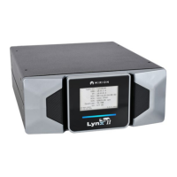
Multi-color LED to indicate instrument status. This indicator is also on the Front Panel
• Green Blinking – Instrument is powered on and in the process of initialization.
• Green Steady On – Instrument is powered on and in operating mode.
• Red Steady On – Instrument has some type of self diagnostic error. The reason for
the error may be confirmed through the appropriate control software (Genie 2000 or
the web browser).
• Red Blinking - During a factory default, the POWER Led will blink red twice at a
slow rate indicating that factory default has been acknowledged. The Red LED can
also blink to indicate a power-fail interrupt.
COMM
Green LED that illuminates each time the instrument has received a command over any
supported communications interface.
HV
Green/Red LED that indicates the state of the selected high voltage power supply:
• Off – High voltage supply is off.
• Green Steady On – High voltage supply is ON and has reached its programmed
voltage.
• Red steady On – High voltage power supply detected fault condition. High voltage
output has been ramped to zero volts. Requires clearing the cause and issue reset-
fault command to unlatch before high voltage power supply can be turned on.
ACQ
Green LED that illuminates Steady On when the instrument is acquiring data.
ICR
Green LED illuminates each time the instrument processes a nuclear event. The intensity
of the LED will vary in proportion to the incoming count rate.

 Loading...