Overview of the Lynx II Web Client User Interface
Lynx II DSA User's Manual – 7096089 75
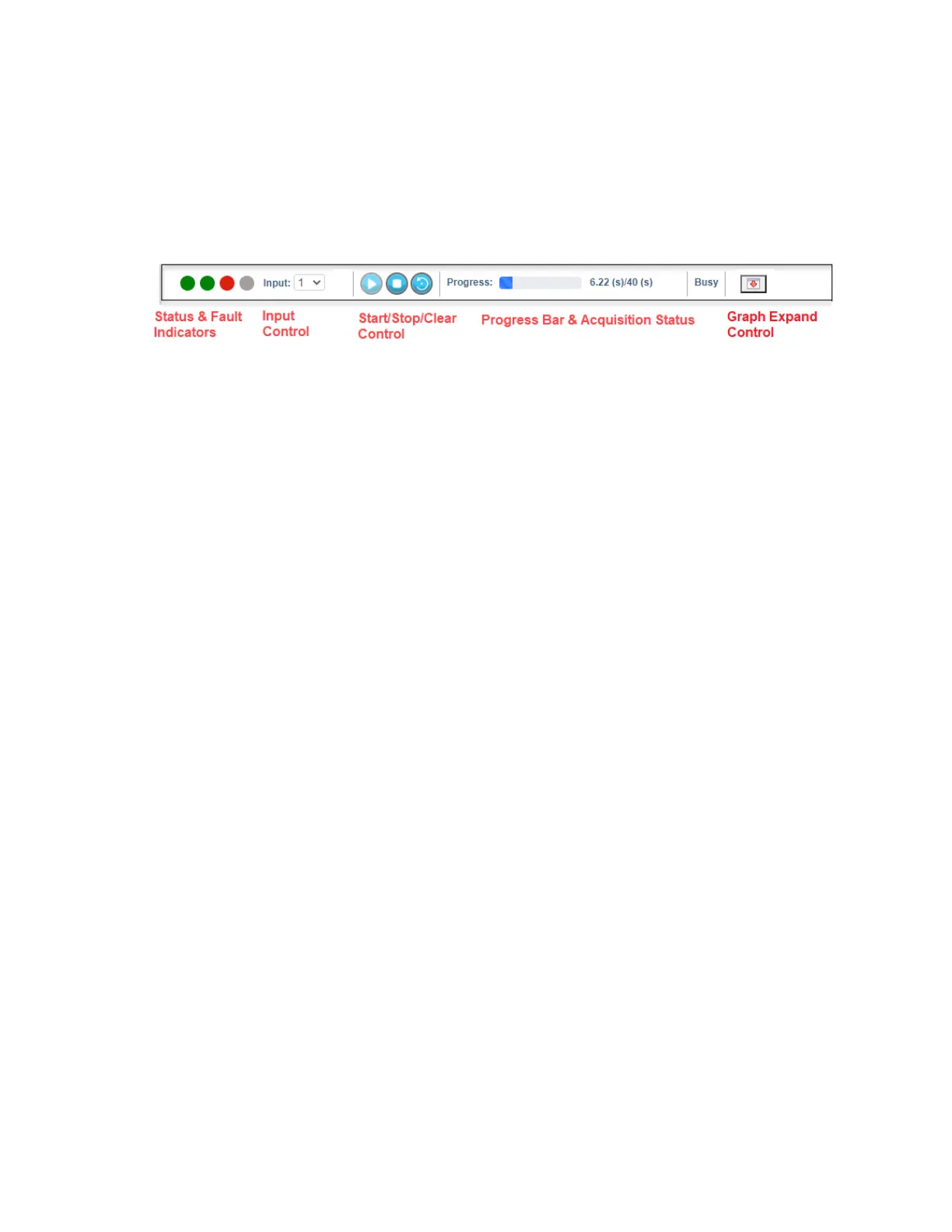
Acquisition Panel
Below the title bar is the acquisition panel which consists of the Status & Fault indicators,
Input and Group control, Start/Stop/Clear control, Progress Bar, and Acquisition Status.
Figure 41: Acquisition Panell
Status & Fault LEDs
From left to right, the LEDs indicate the state of Acquisition, High Voltage Power Supply,
Spectrum Stabilizer, and Auto Pole/zero.
• Acquisition indicates the state of the acquisition for the currently selected input.
• High Voltage Power Supply (HVPS) shows the state of the high voltage power
supply.
• Stabilizer shows the state of the spectrum stabilizer.
• Pole/zero shows the state of automatic pole/zero.
The LEDs change color based on state. The meaning of each color is as follows:
• Red indicates off.
• Green means active.
• Yellow means a fault has occurred with that particular subsystem.
• Orange means waiting for the action to happen.
During a fault condition, a detailed description is displayed with a tooltip when the mouse
hovers over that LED. Holding the shift key while double-clicking on the LED will clear
the fault.
Double-clicking on any of the LEDs will display its settings in the Navigation Panel to the
left.
 Loading...