Chapter 3 Controls and Connectors
18 Lynx II DSA User's Manual - 7096089
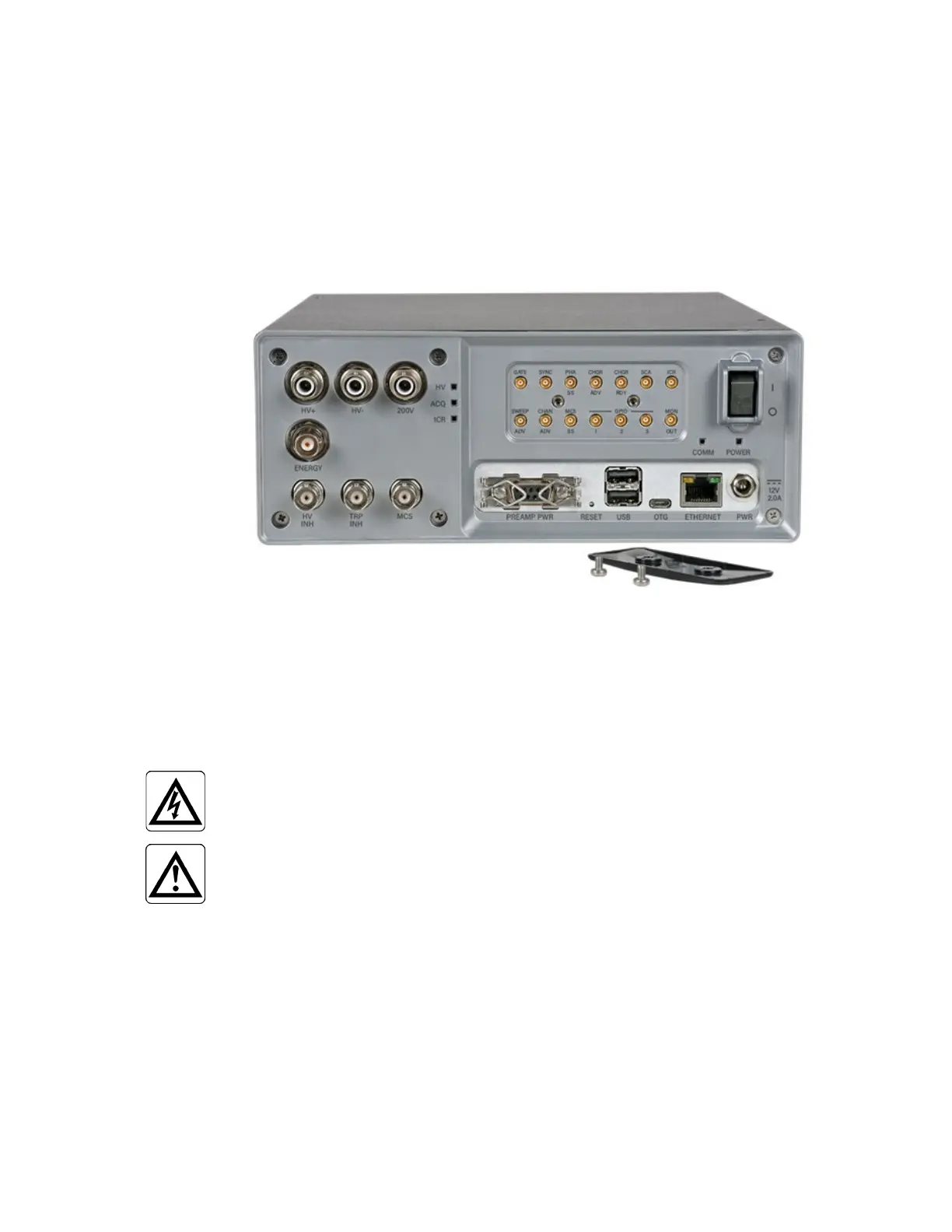
Rear Panel Connectors
The Rear Panel connectors are summarized here. For each connector's technical data, refer
to Specifications on page 135.
Note: You will need to remove the panel to access the Advanced Panel connectors as
shown in Figure 6.
Figure 6 Rear Panel Connectors with Advanced Panel Exposed
High Voltage Power Supply Outputs
The Lynx II provides a triple-ranged high voltage power supply (HVPS) for your
detectors. Only one of the high voltage connectors is active at a time, depending on the
user's settings and the status of their acquisition operations.
High voltage direct current energy can be present on the
High Voltage Power connectors, which can be harmful.
CAUTION:
The ±HV/±200V outputs detailed below shall only be connected
to an external circuit, i.e. a Mirion detector/preamp system via
an HV Coax with a circuit rating of 5kV.
Separate connectors are provided for positive (HV+) and negative (HV–) medium and
high range outputs. A single connector is provided for the ±200 V output.
HV+
Positive high voltage output; range is +200 to +1500 or +1500 to +5000 V.
HV–
Negative high voltage output; range is –200 to –1500 or –1500 to –5000 V.
 Loading...