Acquisition Setup
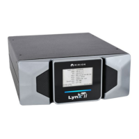
Lynx II DSA User's Manual – 7096089 61
Gate Mode
Select the gating mode, Coincidence, Anti-Coincidence, Combined Adv Coincidence,
Combined Adv Anti-Coincidence, or Off.
• When Off, the coincidence logic is disabled; any signal at the COINC/ANTI input
will be ignored.
• In Coincidence mode, an incoming pulse of the selected polarity within the selected
gate window permits the recording of the event.
• In Anti- Coincidence mode, an incoming pulse of the selected polarity within the
selected gate window inhibits the recording of the event.
• In Combined Adv Coincidence mode, the user can align the input gate with the store
pulse of the event with the Input Gate Delay (µs) and Input Pulse Width (µs). Only
events whose store pulse overlaps the gate (delayed and widened by the Input Gate
Delay and Input Pulse Width fields) of the selected polarity will be recorded in
Memory Group 1. All events (regardless of gating condition) will be recorded in
Memory Group 2.
• In Combined Adv Anti-Coincidence mode, the user can align the input gate with the
store pulse of the event with the Input Gate Delay (µs) and Input Pulse Width (µs).
Only events whose store pulse does not overlap the gate (delayed and widened by
the Input Gate Delay and Input Pulse Width fields) of the selected polarity will be
recorded in Memory Group 1. Gated pulses will be rejected and not stored in
Memory Group 1. All events (regardless of gating condition) will be recorded in
Memory Group 2.
Gate Polarity
Selects the polarity of the gate input. Positive for active-high or Negative for active-low
input.
Gate Delay (µs)
Selects the time window (µs) available for the arrival of the qualifying gate pulse.
Recording of the event is delayed until the qualifying signal occurs or the window time
expires.
Input Gate Delay (µs)
The Input Gate Delay applies a delay value in 0.1 µs resolution to the external gate pulse
to define the gating pulse used by the gating logic. The delay is applied beginning with the
leading edge of the external gate pulse. Input Gate Delay is only enabled for the Combined
Advanced gate modes.
Input Pulse Width (µs)
The Input Pulse Width applies a width value in 0.1 µs resolution to the external gate pulse
to define the gating pulse used by the gating logic. The delay is applied beginning with the
leading edge of the gate pulse; however, the minimum pulse width used by the gating
logic is set by the width of the external gating pulse. Input Pulse Width is only enabled for
the Combined Advanced gate modes.
 Loading...