Chapter 5: Installation
Connecting Cables and Checking Cables to the System
Inter-Tel
®
5000 Installation Manual – Issue 2.4, May 2008 Page 5-69
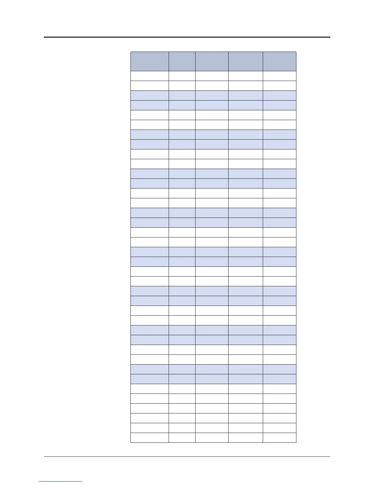
Table 5-9. Station Cable Terminations with a U.S. System
AMPHENOL
Position #
Cable
Pair
DEM-16
Bay 1
Circuit
No.
a
Extension
No.
1
26 W-BL TIP 01.01.01 1000
1BL-WRING
27 W-O TIP 01.02.01 1001
2 O-W RING
28 W-G TIP 01.03.01 1002
3 G-W RING
29 W-BR TIP 01.04.01 1003
4 BR-W RING
30 W-S TIP 01.05.01 1004
5 S-W RING
31 R-BL TIP 01.06.01 1005
6 BL-R RING
32 R-O TIP 01.07.01 1006
7 O-R RING
33 R-G TIP 01.08.01 1007
8 G-R RING
34 R-BR TIP 01.09.01 1008
9BR-RRING
35 R-S TIP 01.10.01 1009
10 S-R RING
36 BK-BL TIP 01.11.01 1010
11 BL-BK RING
37 BK-O TIP 01.12.01 1011
12 O-BK RING
38 BK-G TIP 01.13.01 1012
13 G-BK RING
39 BK-BR TIP 01.14.01 1013
14 BR-BK RING
40 BK-S TIP 01.15.01 1014
15 S-BK RING
41 Y-BL TIP 01.16.01 1015
16 BL-Y RING
42 Y-O NOT USED
17 O-Y NOT USED
43 Y-G NOT USED
18 G-Y NOT USED
44 Y-BR NOT USED
19 BR-Y NOT USED
 Loading...


