Chapter 5: Installation
Connecting Cables and Checking Cables to the System
Page 5-70 Inter-Tel
®
5000 Installation Manual – Issue 2.4, May 2008
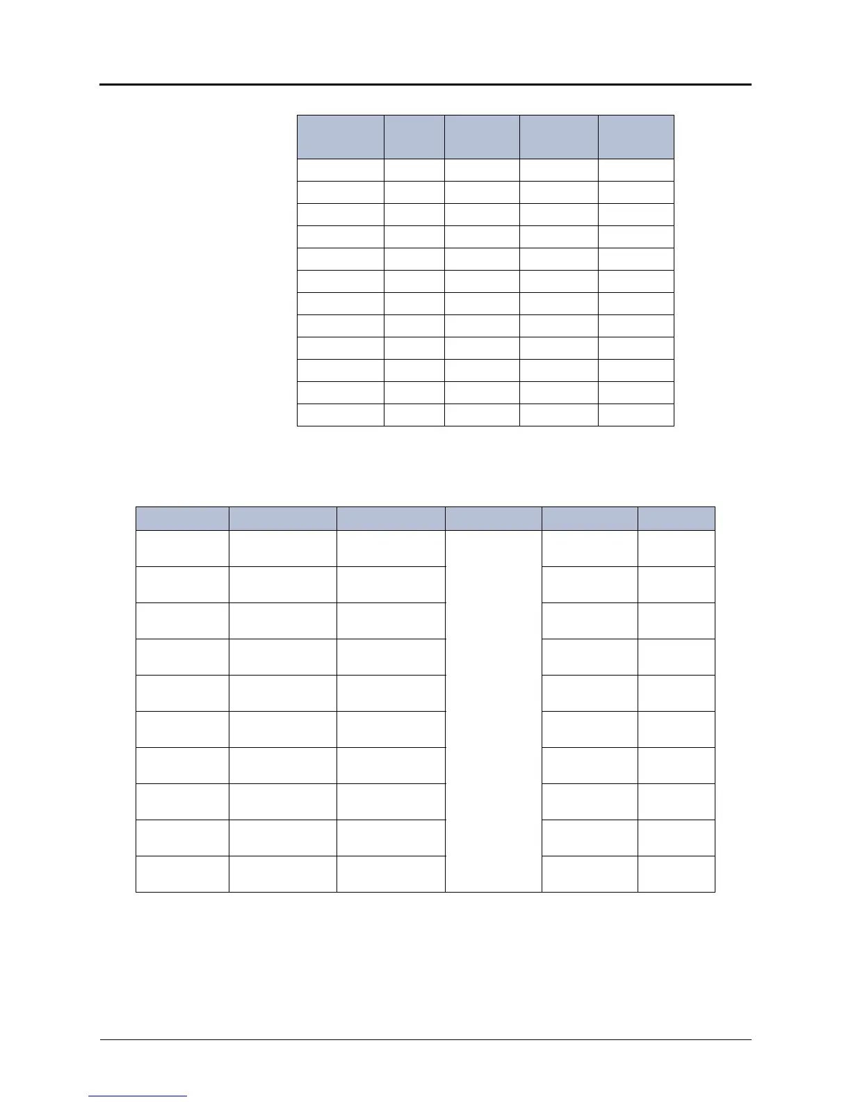
45 Y-S NOT USED
20 S-Y NOT USED
46 V-BL NOT USED
21 BL-V NOT USED
47 V-O NOT USED
22 O-V NOT USED
48 V-G NOT USED
23 G-V NOT USED
49 V-BR NOT USED
24 BR-V NOT USED
50 V-S NOT USED
25 S-V NOT USED
a. The station circuit numbers shown above are for the first DEM-16 in-
stalled in the equipment chassis. (Bay 1). The extension numbers
are the default numbers assigned to those circuits.
Table 5-9. Station Cable Terminations with a U.S. System (Continued)
AMPHENOL
Position #
Cable
Pair
DEM-16
Bay 1
Circuit
No.
a
Extension
No.
1
Table 5-10. Cable Terminations on MDF Blocks [Twin Block Cables] for DEM-16
Cable Pair Color Plug Pin No. BLOCK NO. BLOCK PAIR CIRCUIT
1 White/Blue
Blue/White
1
26
1101.01
2 White/Orange
Orange/White
2
27
202.01
3 White/Green
Green/White
3
28
303.01
4 White/Brown
Brown/White
4
29
404.01
5 White/Gray
Gray/White
5
30
505.01
6Red/Blue
Blue/Red
6
31
606.01
7 Red/Orange
Orange/Red
7
32
707.01
8 Red/Green
Green/Red
8
33
808.01
9 Red/Brown
Brown/Red
9
34
909.01
10 Red/Gray
Gray/Red
10
35
10 10.01
 Loading...


