Chapter 5: Installation
In Professional Display or Associate Display Endpoints
Page 5-186 Inter-Tel
®
5000 Installation Manual – Issue 2.4, May 2008
In Professional Display or Associate Display Endpoints
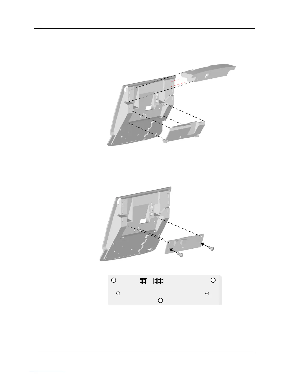
To install a PCDPM in a Professional or Associate Display Endpoints:
1. Press up on the tabs and lift off the cover. Remove the cover and the display endpoint
foot in the back, as shown below.
2. Align the PC Data Port Module over the connector inside of the display endpoint and the
three pins on the outside. Gently press the module into place until the connector is
securely positioned into place, as shown below.
3. Attach the module to the display endpoint using the two mounting screws.
4. Plug the appropriate end of the PCDPM-to-MDPM interface cable, part no. 813.1566,
into the MDPM connector (J1), shown above, on the module. The other end of the cable
will later be attached to the MDPM after it is installed.
Pin 1 of the cable, indicated by the stripe on the edge of the cable, must correspond to
pin 1 on the MDPM connector, indicated by the notch silk-screened on the module.
BACK OF DISPLAY ENDPOINT
DISPLAY ENDPOINT
COVER
FOOT
BACK OF DISPLAY ENDPOINT
PCDPM