Chapter 5: Installation
In Model 8520 or Model 8560 Endpoints
Inter-Tel
®
5000 Installation Manual – Issue 2.4, May 2008 Page 5-187
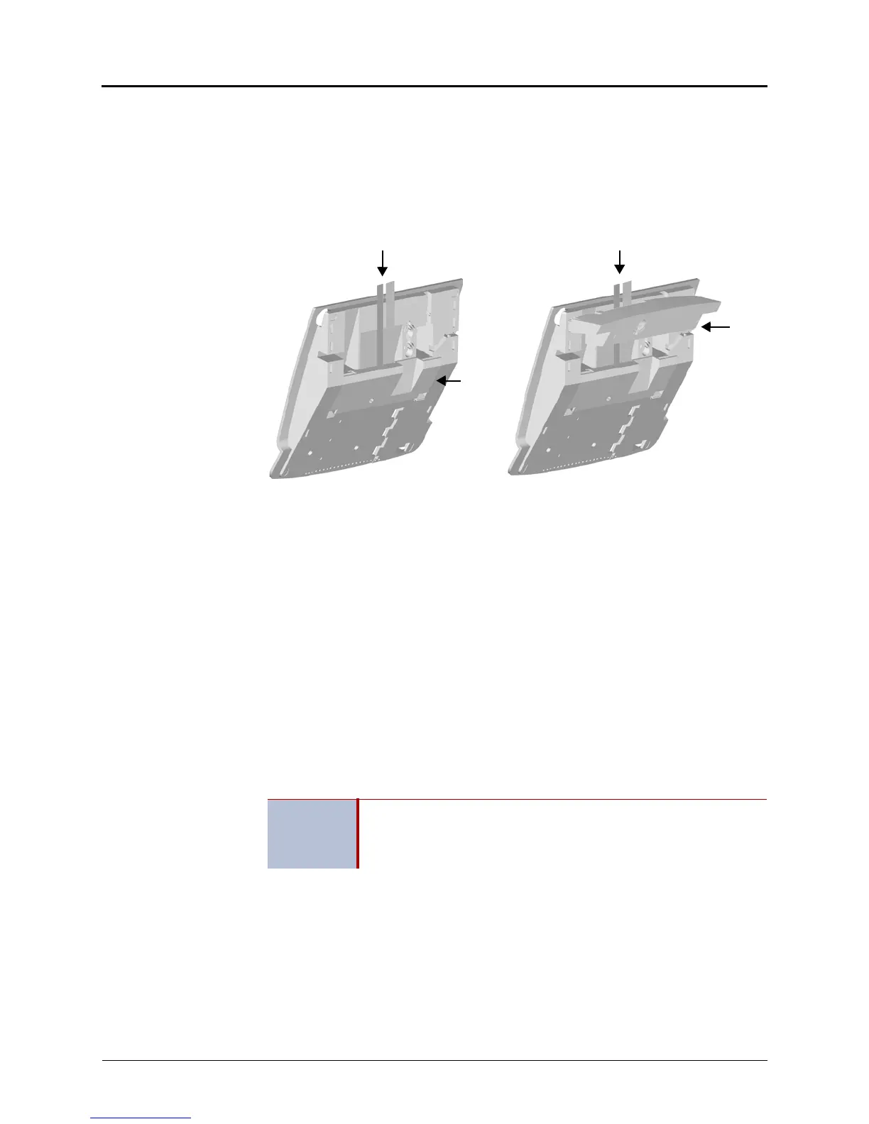
5. Carefully thread the cables connected to the PCDPM through the slots on the access
panel, and re-attach the access panel to the endpoint. Make sure the cables exit through
the slot between the cover and the bottom of the display endpoint, as shown below on
the left.
6. Place the cables flat against the endpoint and carefully place the foot over the cables, as
shown below on the right. For sample display endpoint PCDPM cable connections, see
Figure 5-73 on page 5-189.
In Model 8520 or Model 8560 Endpoints
For installation diagrams, see Figure 5-74 on page 5-190 and Figure 5-75 on page 5-190.
To install the PCDPM in a Model 8520 or 8560 endpoint:
1. Unplug the line cord and headset from the modular jacks on the back of the endpoint.
2. Open the endpoint base to a fully extended position.
3. Gently slide the access panel off the endpoint to expose the PCDPM pin connector (J10)
on the endpoint control board.
4. Align the PCDPM J3 connector with the board J10 connector and plug the PCDPM into
place on the endpoint board (see Figure 5-74 on page 5-190).
If a Modem Data Port Module will be attached to the PC Data Port Module, plug the
appropriate end of the PCDPM-to-MDPM interface cable into the 14-pin (J1) MDPM
connector on the PCDPM. (The other end of the cable will later be attached to the
MDPM after it is installed.)
5. Carefully thread the cables connected to the PCDPM through the slots on the access
panel. Re-attach the access panel to the endpoint.
6. Secure the access panel to the PCDPM and the endpoint using the mounting screw
supplied in the PCDPM kit.
IMPORTANT
If the correct end of the cable is not connected into J1, the attached
device will not function properly. Make sure that the notched side of
the cable’s plastic connector faces away from the PCDPM board, and
the smooth side lies flat against it.