Chapter 5: Installation
In Model 8520 or Model 8560 Endpoints
Page 5-188 Inter-Tel
®
5000 Installation Manual – Issue 2.4, May 2008
7. Because a Modem Data Port Module will be attached to the PC Data Port Module, see
the instructions on page 5-190. The only purpose of installing a PCDPM in a digital
endpoint is to provide the copper path between the MDPM and a DSS/BLF unit. There is
no need to install a PCDPM without also installing an MDPM.
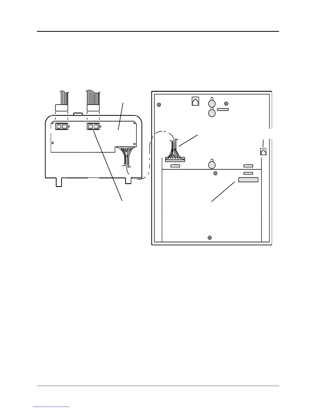
Figure 5-71. PCDPM Installation in an Executive or Standard Display Endpoint
BACK OF DIGITAL ENDPOINTINSIDE OF BASEPLATE
If the endpoint will be wall-mounted, open
the back of the endpoint and reroute the
Module-to-Keyset Interface cable through
this knockout over to connector J3 on the
control board.
TO CHASSIS
J3
TO
HANDSET
PCDPM
RS232
CONNECTOR
MDPM
CONNECTOR
To Modem Data
TO DSS/BLF UNIT OR
PC/OUTPUT DEVICE
J1
P1
Older PCDPMs, part no. 550.3014, require AC transformers when they are connected to DSS/BLF units only.
PCDPMs do not require AC transformers when they are used for off-hook voice announce only or have
attached MDPMs. For a diagram of AC transformer requirements, see Figure 5-70 on page 5-184. Also, some
early PCDPM-to-MDPM cables may have the stripe on the wrong edge. If the MDPM does not respond prop-
erly, try reversing the connector on the PCDPM.
J2
Port Module