OPERATION
© 2014 Mold-Masters (2007) Limited. All Rights Reserved.
Revised 1 Oct, 2014
6-47
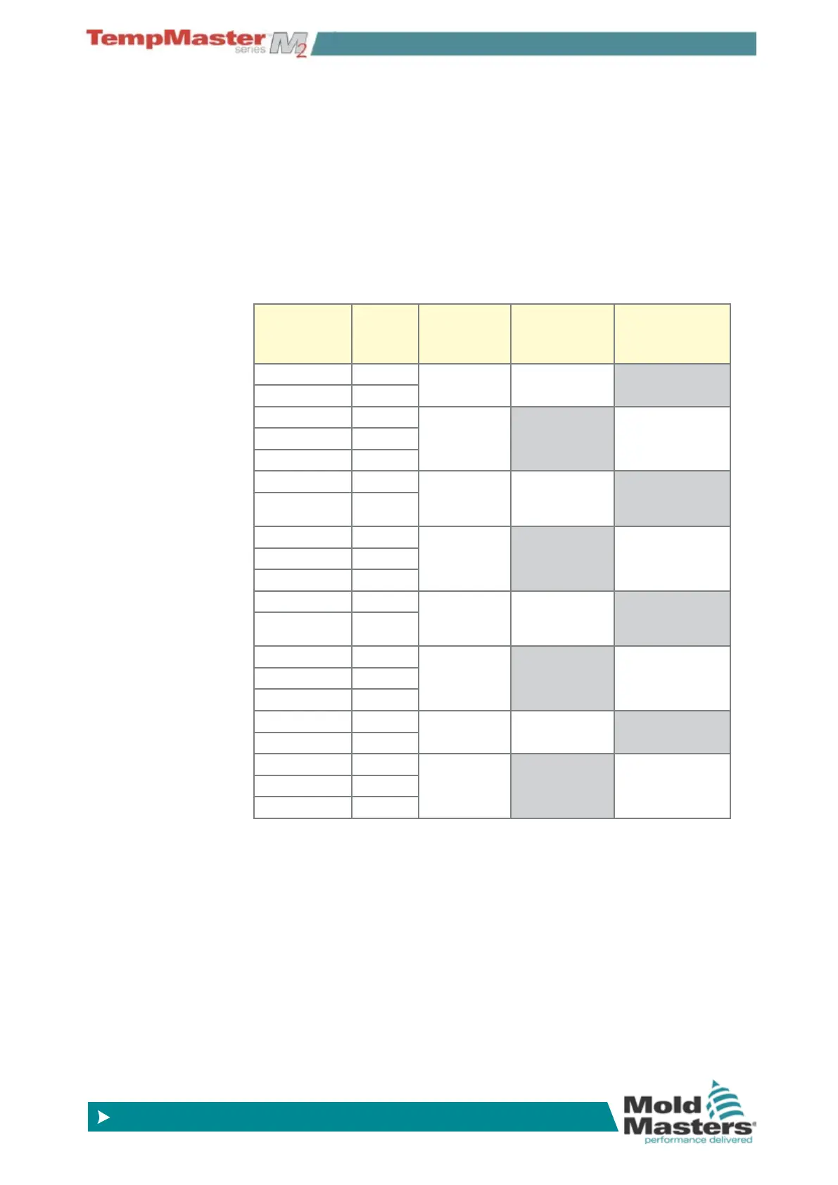
6.29 Default Input/Output Selection and
connector pin table
The standard interface is a Harting STA 20-pin female connector
within an H-A16 housing.
Even though input/outputs channels may be individually congured to
assume different functions, the default options are as shown in the fol-
lowing table along with the connector-pin congurations.
I/O Connection
Description STA 20
pin no.
Circuit Default
Input
Function
Default
Output
Function
Input 1 1 Input 1 Go to RUN
Mode
Input 1 2
NO Contact 1 3 Output 1 Injection Disable
MC Contact 1 4
NC Contact 1 5
Input 2 6 Input 2 Go to
STANDBY
Mode
Input 2 7
NO Contact 2 8 Output 2 Temperature
Disturbance
MC Contact 2 9
NC Contact 2 10
Input 3 11 Input 3 Go to
STARTUP
mode
Input 3 12
NO Contact 3 13 Output 3 Boost
MC Contact 3 14
NC Contact 3 15
Input 4 16 Input 4 Go to STOP
Mode
Input 4 17
NO Contact 4 18 Output 4 Spare/Inactive
MC Contact 4 19
NC Contact 4 20