SETUP
© 2014 Mold-Masters (2007) Limited. All Rights Reserved.
Revised 1 Oct, 2014
5-5
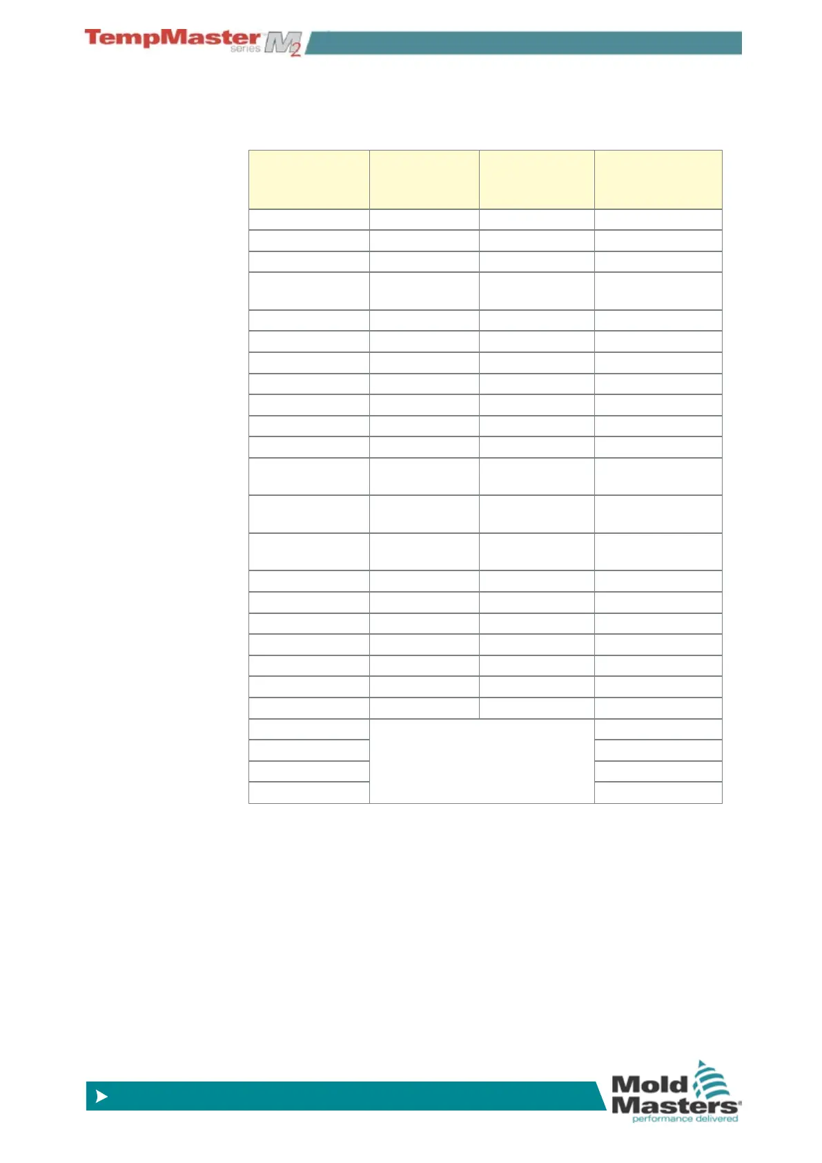
5.4 Pre-congured Setup values
The table below shows the whole Setup chart and the differing values
that are given to both Probe and manifold zones.
Parameter Probe and
Manifold
Cards
Other
Monitoring
Cards
Synchro/ Spear
Rack Address slot address slot address slot address
Alias blank blank blank
TC Open Mode Normal blank Normal
Standby & Boost
Temp
0ºC or 0ºF blank 0ºC or 0ºF
Boost Time 0 blank 0
Master Zone blank blank blank
Warn Hi & Lo 5ºC or 9ºF blank 5ºC or 9ºF
Alarm Hi & Lo 25ºC or 45ºF 25ºC or 45ºF 25ºC or 45ºF
Alarm Power Off Off Off
Alarms Active C,B,I C,B,I C,B,I
Alarm Time 10 Secs 10 Secs 10 Secs
Max Set-point
Setting
450ºC or 842ºF 450ºC or 842ºF 450ºC or 842ºF
Min Set-point
Setting
0ºC or 32ºF blank 0ºC or 32ºF
Max Power
Setting
100% blank 100%
T/C Offset Value 0ºC or 0ºF blank 0ºC or 0ºF
Speed Auto blank Auto
Sensor J-Type blank J-Type
Display Group 1 blank 1
Startup Stage off off off
Shutdown Stage off off off
Reading Avg 0 0 0
Pre-heat These Columns do not appear on
the Setup page unless a control
card is congured to be a Synchro/
Tip type
20%
Boost 40%
Delay 5.0 Secs
Time 5.0 Secs