Wiring a Signaling Line Circuit (SLC) Installation
AFP-200 PN 15511:H2 10/14/2002 47
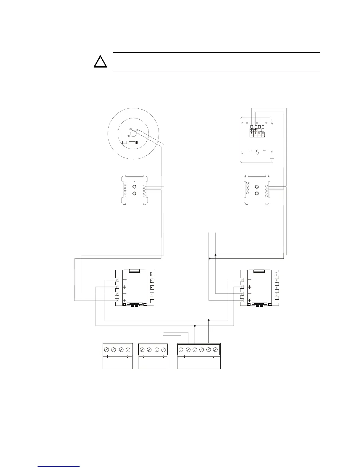
Figure 27 shows typical wiring of a supervised and power-limited two-wire SLC that
meets NFPA 72 Style 4 requirements.
CAUTION: Terminate shield drain wire according to the instructions in “SLC
Shield Termination” on page 43.
Note: ISO-X devices are not required to meet NFPA Style 4. You can install a
maximum of 25 devices, detectors, and modules between isolator modules, or isolator
detector mounting base.
Figure 27 Two-wire SLC (Style 4)
!!
1 2 3 4
TB4
TB5 TB6
TX REF RX REF
OUT OUT IN IN
1 2 3 4 5 6
A B B+ A+ B- A-
2(+)
1(-)
3
LOOP ADDRESS
TYP E
Low
Med
High
1
2
3
4
1
2
3
4
90
81
72
63
54
-
+
+-
90
81
72
63
54
-
+
+
-
CPU
Connect (+) to TB 6-3
Connect (–) to TB 6-5
B710LP Detector Base
Use with FSP, FSI, and FST
Series intelligent detectors
Separate T-Tap to
other SLC devices
no connection
NBG-12LX
Monitor ModuleControl or Relay
Module
Loop Isolator Module Loop Isolator Module
AFP200-SLC-6.cdr
Technical Manuals Online! - http://www.tech-man.com
 Loading...


